Ventilation load-reducing apparatus and vehicle air conditioner using the same

Inactive Publication Date: 2011-06-16
CALSONIC KANSEI CORP
View PDF4 Cites 5 Cited by
  • Summary
  • Abstract
  • Description
  • Claims
  • Application Information

AI Technical Summary

Benefits of technology

[0023]According to the present invention, it is possible to achieve a ventilation load-reducing apparatus, which has

Problems solved by technology

However, today, a low-heat-generating engine or the like has been used along with highly prom

Method used


Image

  • Ventilation load-reducing apparatus and vehicle air conditioner using the same
  • Ventilation load-reducing apparatus and vehicle air conditioner using the same
  • Ventilation load-reducing apparatus and vehicle air conditioner using the same

Examples


Example

[0027]Hereinafter, an embodiment for realizing a ventilation load-reducing apparatus of the present invention and a vehicle air conditioner using the same will be described with reference to the accompanying drawings.

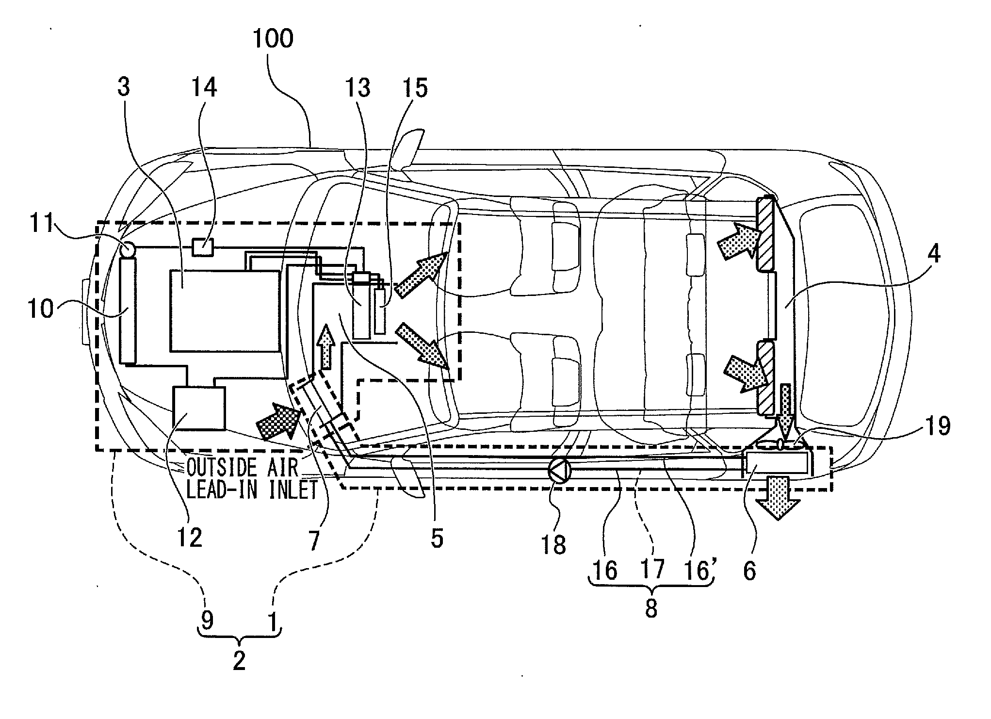
[0028]FIG. 1 is a plan perspective view showing a vehicle 100 on which a ventilation load-reducing apparatus 1 for explaining an embodiment of the present invention and a vehicle air conditioner 2 using the same are mounted as viewed down from above.

[0029]In addition, in the present embodiment, not about the vehicle air conditioner, which performs the heating by using a heat pump cycle but about the vehicle air conditioner, which performs the heating by using an apparatus (a heated water producing apparatus 3) configured to produce heated water will be described.

[0030]In the FIG. 1, the plan perspective view shows a state where a forward direction of the vehicle 100 is indicated as a leftward direction.

[0031]As shown in FIG. 1, on a rear side of the vehicle 100, an insi...


PUM


Abstract

A ventilation load-reducing apparatus, which has a simple structure and is capable of further improving the efficiency of the heat recovery, and a vehicle air conditioner using the same are proposed. The ventilation load-reducing apparatus includes an inside air lead-out path 4 for ventilation which leads air of a vehicle-interior out of a vehicle from a rear side of the vehicle-interior, an outside air lead-in path 5 which leads outside air into a front side of the vehicle-interior, a ventilation heat recovery device 6 which recovers heat from the air led out through the inside air lead-out path 4, a recovered heat radiator 7 which releases the heat on the air led in through the outside air lead-in path 5, and a heat transmitter 8 which transmits the heat between the ventilation heat recovery device 6 and the recovered heat radiator 7. The ventilation load-reducing apparatus is independent of a refrigerant circulating system 9 of a vehicle air conditioner 2.

Description

TECHNICAL FIELD[0001]The present invention relates to a ventilation load-reducing apparatus and a vehicle air conditioner using the same, and especially, to a ventilation load-reducing apparatus which reduces a load of ventilation when heating and a vehicle air conditioner using the same.BACKGROUND ART[0002]In general, when heating a vehicle-interior by a heater, the heating has been performed by guiding engine-cooling water which is heated when cooling an engine to a heater core provided in the vehicle-interior and warming up air by the heater core.[0003]However, today, a low-heat-generating engine or the like has been used along with highly promoted streamlining of an engine so that using exhaust heat of the engine has become difficult. In addition, in a car such as an electric car or the like, on which an engine is not mounted, it is necessary to perform the heating without using the exhaust heat from the engine.[0004]Therefore, conventionally, an air conditioning cycle used as a...

Claims


Application Information

Patent Timeline
IPC IPC(8): B60H1/26
CPCB60H1/00564B60H1/248B60H1/03B60H1/246B60H1/039
Inventor NAKAJO, KAZUOYOSHIOKA, HIROKIFUJITA, TAKASHI
Owner CALSONIC KANSEI CORP
Why Eureka
Try Eureka