Expandable transapical sheath and method of use

a transapical and expandable technology, applied in the field of expandable transapical sheaths and methods of use, can solve the problems of suboptimal and crude current access systems, and achieve the effects of reducing tissue trauma, improving healing of the myocardium, and less blood loss

Active Publication Date: 2011-06-16
ONSET MEDICAL CORP
View PDF99 Cites 51 Cited by
  • Summary
  • Abstract
  • Description
  • Claims
  • Application Information

AI Technical Summary

Benefits of technology

[0013]In one embodiment, the sheath can be used as an introducer for therapeutic or diagnostic catheter systems or devices. The expandable sheath has the clinical benefit of being able to radially dilate tissue, thus causing minimal tearing and tissue trauma relative to surgical incisions that generally tear tissue in order to expand. The expandable sheath can be used to assist with percutaneous, port-access, or minimally invasive cardiac access procedures in that it allows for a small diameter access to the cardiac chambers that can then be expanded into a size large enough for introduction of large interventional, therapeutic, or diagnostic devices therethrough. The expandable arterial access sheath can reduce procedure time, procedure cost, trauma to the patient, and improve patient outcomes.
[0042]Some of the main reasons for the malleable embodiments include control over cross-sectional shape, ability to embed the reinforcement in the polymer layers without needing to create some difficult to manufacture decoupling of the polymer and the reinforcement, the high strength of the sheath following placement, and prevention of lumen re-collapse caused by body tissue. The ability of this device to remodel to the desired shape to generate a superhighway for placement of implants and other medical devices is superior to anything available today. Furthermore, the device provides a relatively smooth interior lumen which allows passage of instruments and implants of very large size without excessive binding or friction. No other sheath exists today that has these benefits.

Problems solved by technology

Current access systems are relatively crude and suboptimal for transapical procedures.

Method used


Image

  • Expandable transapical sheath and method of use
  • Expandable transapical sheath and method of use
  • Expandable transapical sheath and method of use

Examples


Embodiment Construction

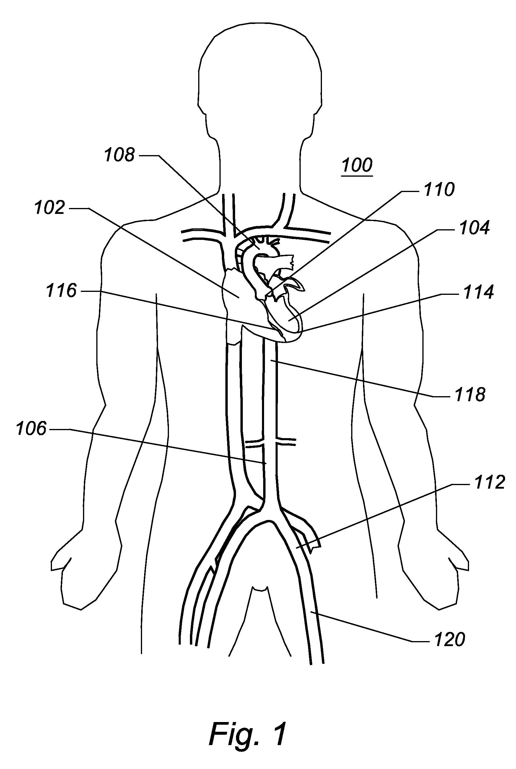
[0079]As used herein, a catheter, introducer, or sheath can be described as an axially elongate structure having a proximal end, a distal end, and a lumen extending partially, or completely, therethrough. As used herein, the terms proximal and distal refer to directions or positions along a longitudinal axis of a catheter or medical instrument. Proximal refers to the end of the catheter or medical instrument closest to the operator, while distal refers to the end of the catheter or medical instrument closest to the patient. For example, a first point is proximal to a second point if it is closer to the operator end of the catheter or medical instrument than the second point. However, the terms anatomically proximal and anatomically distal refer to orientations within the body. For example, a point is more anatomically distal if it is further from the heart than a point described as anatomically proximal.

[0080]FIG. 1 is a schematic frontal (anterior) illustration (looking posteriorly...


PUM


Abstract

Disclosed is an expandable transluminal sheath, for introduction into the body while in a first, small cross-sectional area configuration, and subsequent expansion of at least a part of the distal end of the sheath to a second, enlarged cross-sectional configuration. The sheath is configured for use in the vascular system and has utility in the introduction and removal of implant delivery catheters. The access route is through the ventricular myocardium, more specifically at the left ventricular apex, into the aortic root. The distal end of the sheath is maintained in the first, low cross-sectional configuration during advancement to the arteries into the aorta. The distal end of the sheath is subsequently expanded using a radial dilatation device, which is removed prior to the introduction of implant delivery catheters. In an exemplary application, the sheath includes a supported proximal end, a supported distal end, and a collapsible center section. Certain configurations of the sheath are capable of being inserted in a first, small cross-sectional configuration, being expanded diametrically to a second, larger cross-sectional configuration, and then being reduced to a diametrically small size for removal.

Description

PRIORITY CLAIM [0001]This application is a continuation of International Patent Application No. PCT / US2009 / 044030, entitled “Expandable Transapical Sheath and Method of Use,” filed on May 14, 2009, which is a continuation-in-part of U.S. patent application Ser. No. 12 / 258,245, entitled “Expandable Transapical Sheath and Method of Use,” filed on Oct. 24, 2008, which claims priority from U.S. Provisional Patent Application No. 61 / 127,619, filed May 14, 2008, entitled “Expandable Iliac Sheath and Method of Use,” the entirety of which are hereby incorporated herein by reference.BACKGROUND OF THE INVENTION[0002]1. Field of the Invention[0003]The invention relates to medical methods and devices and, more particularly, to methods and devices for accessing the chambers of the heart through a minimally invasive myocardial puncture.[0004]2. Description of the Related Art[0005]Considerable effort and money is being directed toward replacement of diseased or damaged cardiac valves through minim...

Claims


Application Information

Patent Timeline
Patent Type & Authority Applications(United States)
IPC IPC(8): A61M29/00
CPCA61F2/2412A61F2/2418A61F2/2433A61F2/2436A61M25/0053A61M2025/0681A61M25/10A61M25/1011A61M25/104A61M29/02A61M2025/0024A61M25/0662
Inventor BISHOP, JOSEPHLENKER, JAYNANCE, EDWARD J.NGUYEN, HUAN T.JONES, MARK T.
Owner ONSET MEDICAL CORP
Why Eureka
Try Eureka