Automated Pad Ring Generation for Programmable Logic Device Implementation of Integrated Circuit Design

a technology of integrated circuit design and pad ring generation, which is applied in the direction of cad circuit design, error detection/correction, instruments, etc., can solve the problems of increasing complexity, allowing more extensive testing and/or more complex testing, and increasing complexity of integrated circuit design and testing

Inactive Publication Date: 2011-06-16
APPLE INC
View PDF31 Cites 28 Cited by
  • Summary
  • Abstract
  • Description
  • Claims
  • Application Information

AI Technical Summary

Benefits of technology

[0007]In an embodiment, a method to automatically generate a pad ring for a programmable logic device implementation of an integrated circuit is contemplated. The pad ring that will be used in the integrated circuit itself may include pad logic (e.g. to support boundary scan and other forms of testing), custom driver / receiver circuitry, etc. The pad ring in the programmable logic device, on the other hand, may be predetermined as part of the production of the programmable logic device. The pad ring generation may include removing the pad logic and other pad-related circuitry from one or more design files that represent the integrated circuit, as well as mapping the input, output, and input / output signals of the integrated circuit to the available programmable logic device pads.

Problems solved by technology

Integrated circuit design and testing continues to grow in complexity as the complexity of the integrated circuit itself increases.
With every new generation of integrated circuit fabrication technology, the number of transistors that can be included on a given integrated circuit chip increases, which further contributes to the increased complexity.
Programmable logic device implementations typically operate at higher speeds than software simulations, permitting more extensive testing and / or more complex testing.
The process is error-prone and often results in lost time determining why the programmable logic device implementation is not working.

Method used


Image

  • Automated Pad Ring Generation for Programmable Logic Device Implementation of Integrated Circuit Design
  • Automated Pad Ring Generation for Programmable Logic Device Implementation of Integrated Circuit Design
  • Automated Pad Ring Generation for Programmable Logic Device Implementation of Integrated Circuit Design

Examples


Embodiment Construction

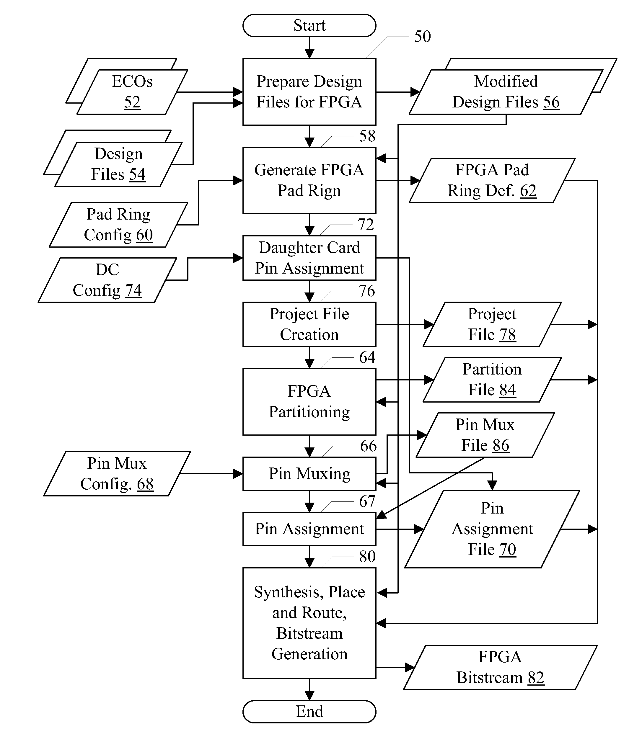
HDL Design File to Programmable Logic Device Methodology Overview

[0028]As mentioned above, the design of an integrated circuit may be described in one or more design files, using an HDL. Exemplary HDLs that may be used in various embodiments include Verilog, VHDL, etc. Generally, HDLs may support the description of the integrated circuit at a high level (e.g. as logic equations) that may be convenient for human generation and consumption. In one embodiment, the design descriptions may be register-transfer level (RTL) descriptions expressed in an HDL. The description in the design files, when taken as a whole, describe the integrated circuit. The division into multiple design files may provide for convenient editing and change tracking. For example, each component of the integrated circuit may be represented by one or more design files.

[0029]The design files may be processed in a variety of ways. For example, the design files may be compiled to a variety of target platforms for testi...


PUM


Abstract

In an embodiment, a method to automatically generate a pad ring for a programmable logic device implementation of an integrated circuit is contemplated. The pad ring that will be used in the integrated circuit itself may include pad logic (e.g. to support boundary scan and other forms of testing), custom driver/receiver circuitry, etc. The pad ring in the programmable logic device, on the other hand, may be predetermined as part of the production of the programmable logic device. The generation may include removing the pad logic and other pad-related circuitry from one or more design files that represent the integrated circuit, as well as mapping the input, output, and input/output signals of the integrated circuit to the available programmable logic device pads.

Description

BACKGROUND[0001]1. Field of the Invention[0002]This invention is related to the field of integrated circuit design and, more particularly, to implementing an integrated circuit design in one or more programmable logic devices.[0003]2. Description of the Related Art[0004]Integrated circuit design and testing continues to grow in complexity as the complexity of the integrated circuit itself increases. With every new generation of integrated circuit fabrication technology, the number of transistors that can be included on a given integrated circuit chip increases, which further contributes to the increased complexity.[0005]A programmable logic device implementation of all or portions of an integrated circuit design is one option that can be used during the development of an integrated circuit. Programmable logic device implementations typically operate at higher speeds than software simulations, permitting more extensive testing and / or more complex testing. For example, running the act...

Claims


Application Information

Patent Timeline
Patent Type & Authority Applications(United States)
IPC IPC(8): G06F17/50
CPCG06F17/5054G06F30/34
Inventor CHEN, CHIH-ANG
Owner APPLE INC
Why Eureka
Try Eureka