
Oil separator

a technology of oil separator and separator body, which is applied in the direction of separation process, liquid fuel engine, machine/engine, etc., can solve the problems of low lubricating efficiency, insufficient oil separation, and low suction speed of refrigeran

Inactive Publication Date: 2011-06-23
DOOWON TECHN COLLEGE +1
View PDF2 Cites 17 Cited by
  • Summary
  • Abstract
  • Description
  • Claims
  • Application Information

AI Technical Summary

Benefits of technology

"The present invention relates to an oil separator for a scroll compressor that improves oil separating performance by enhancing the centrifugal force. The oil separator is designed to separate refrigerant into oil and gas through the principle of centrifugal separation, and to prevent the re-mixing of oil and gas during the separation process. The oil separator includes a cylindrical space with a refrigerant introducing pipe and gas and oil branch pipes that guide the separated refrigerant in a natural manner. The cross-sectional area of the refrigerant passage in the oil separator is made constant to maximize the centrifugal force and improve oil separating efficiency."

Problems solved by technology

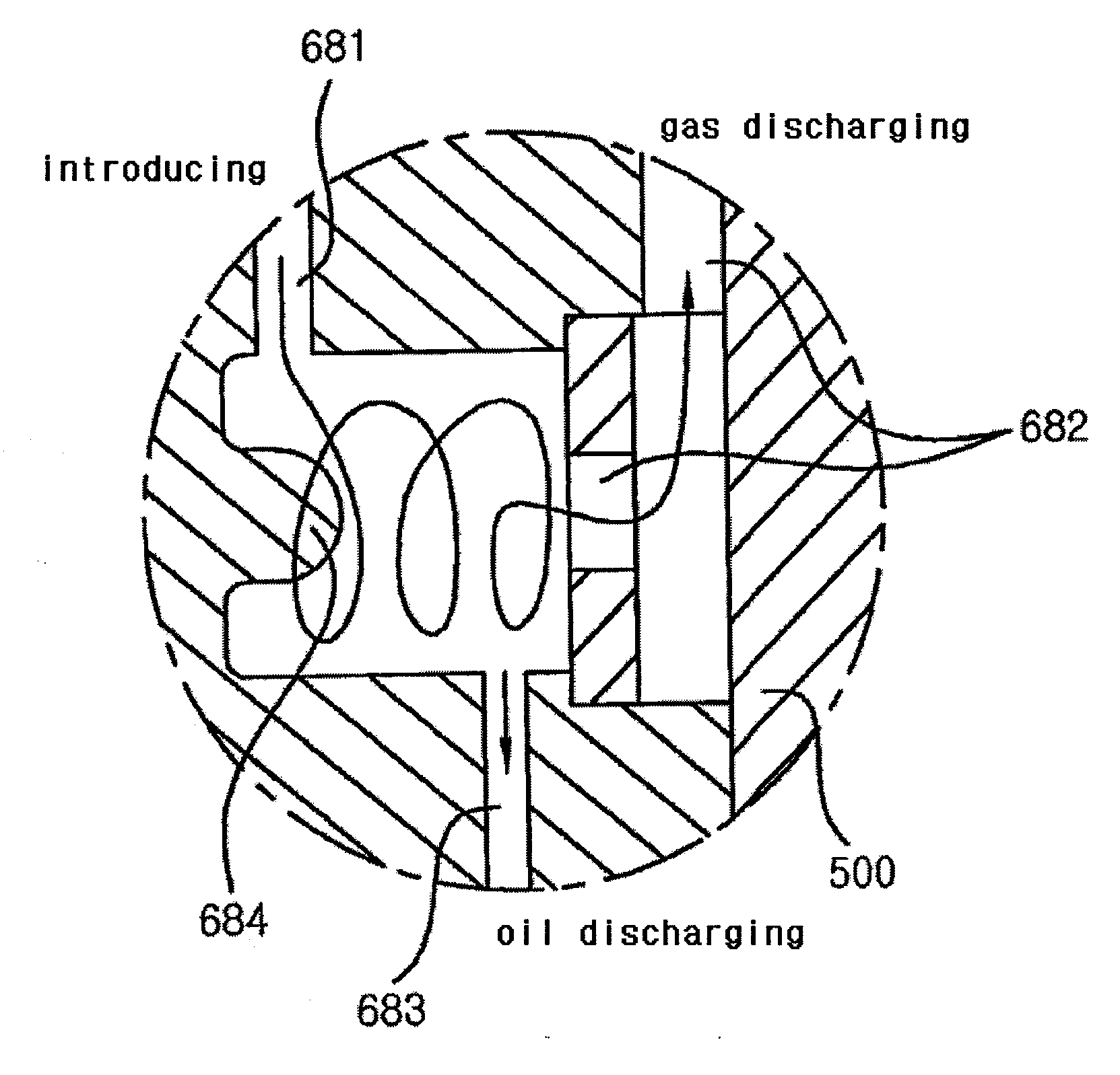
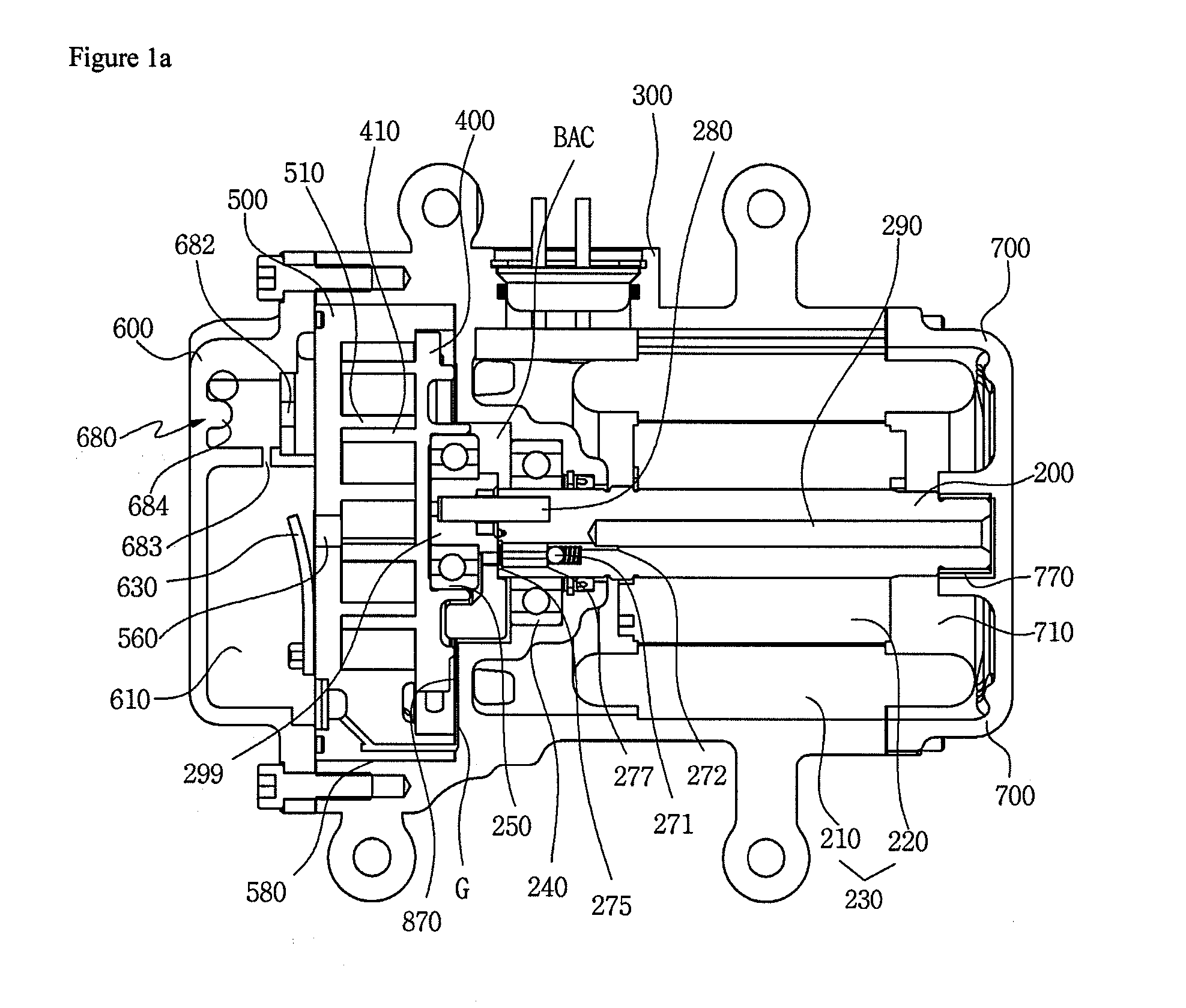
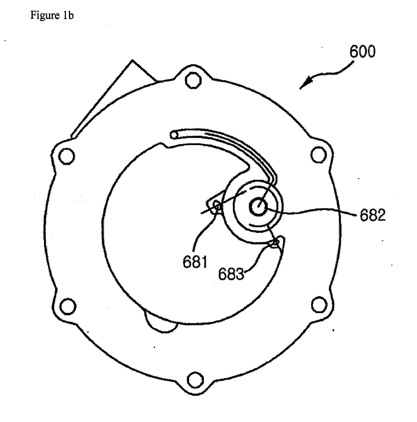
However, in the conventional scroll compressor, since the cross-sectional area of the refrigerant passage in the oil separator 680 is made constant such that the magnitude of the centrifugal force becomes almost constant as the refrigerant proceeds, oil cannot be sufficiently separated when the suction speed of the refrigerant is relatively low.
In this case, as the oil is contained in the refrigerant gas when it is discharged, lubricating efficiency lowers, deteriorating the performance of the compressor.
Further, as the cross-sectional area of the refrigerant passage deviating from the guide boss 684 is large, fluid velocity cannot be sufficiently secured, lowering an oil separating effect due to a centrifugal force.

Method used


Image

  • Oil separator
  • Oil separator
  • Oil separator

Examples


Embodiment Construction

[0035]Hereinafter, exemplary embodiments of the present invention will be described in detail with reference to the accompanying drawings.

[0036]FIG. 2 is a longitudinal sectional view illustrating the structure of a scroll compressor including an oil separator according to the present invention. FIG. 3 is a transverse sectional view illustrating an oil separator according to the present invention. FIG. 4 is a longitudinal sectional view taken along a section A-A of FIG. 3 as an embodiment of the present invention. FIG. 5 is a longitudinal sectional view taken along a section A-A of FIG. 3 as another embodiment of the present invention.

[0037]Hereinafter, the embodiments of the present invention will be described in detail with reference to FIGS. 2 to 5.

[0038]As illustrated in FIG. 2, the scroll compressor CP according to the present invention includes a housing 10, a drive unit 20 installed within the housing 10 to generate a rotational force, a fixed scroll 31 and a orbiting scroll ...


PUM

PropertyMeasurementUnit
inner diameteraaaaaaaaaa
volumeaaaaaaaaaa
rotational forceaaaaaaaaaa

Abstract

An oil separator comprises: a hollow outer body having an inlet and a drain hole; and an inner tube spaced apart from an inner peripheral surface of the outer body and having a discharge hole at a center thereof. The inner peripheral surface of the outer tube guides oil toward the drain hole opposite to the discharge hole. The present invention provides an oil separator that maximizes an oil separating effect through enhancement of a centrifugal force. The present invention also provides an oil separator that maximizes an oil separating performance by preventing gas and oil from being remixed by guiding the flow direction of the oil separated by a centrifugal force using a spiral portion and a taper.

Description

TECHNICAL FIELD[0001]The present invention relates to an oil separator, and more particularly to an oil separator that used in a scroll compressor to maximize oil separating performance by separately discharging oil and gas in a natural manner using the principle of centrifugal separation.BACKGROUND ART[0002]In general, a scroll compressor includes a fixed scroll having a spiral scroll wrap and fixed irrespective of rotation of a drive shaft and an orbiting scroll also having a spiral scroll wrap and configured to orbit as the driven shaft rotates. Such a scroll compressor is an apparatus adapted to compress a refrigerant through a pocket formed between the scroll wraps such that its volume varies as the orbiting scroll orbits with respect to the fixed scroll with the refrigerant being suctioned into a compression chamber formed between the fixed scroll and the orbiting scroll.[0003]An example of a conventional scroll compressor is disclosed in Korean Patent Application No. 10-2006-...

Claims


Application Information

Patent Timeline
Patent Type & Authority Applications(United States)
IPC IPC(8): B01D45/08B01D45/16
CPCF01M2013/0427F04C29/026F04C18/0215F01M13/04F01M13/00B01D17/02F01M11/08
Inventor LEE, GEONHOKOO, INHWEHAN, YOUNG CHANG
Owner DOOWON TECHN COLLEGE
Learn More