
Device for cooling a coolant, circuit for charging an internal combustion engine, and method for cooling a substantially gaseous charging fluid for charging an internal combustion engine

a charging circuit and charging device technology, applied in the direction of machines/engines, refrigeration components, lighting and heating apparatus, etc., can solve the problems of sensitive reaction of fuel consumption with lower output of internal combustion engines, the limit temperature is reached more quickly, etc., and achieve the effect of effective utilization and effective supply of charge fluid cooling outpu

Inactive Publication Date: 2011-06-23
BEHR GMBH & CO KG
View PDF17 Cites 25 Cited by
  • Summary
  • Abstract
  • Description
  • Claims
  • Application Information

AI Technical Summary

Benefits of technology

[0009]It is therefore an object of the present invention to provide a device for cooling a coolant that is provided for cooling a charging fluid for charging an internal combustion engine, as well as a circuit for charging an internal combustion engine. An additional object is to specify a method for cooling a substantially gaseous charging fluid provided for charging an internal combustion engine. The devices and the method are meant to be capable of more effectively providing charge fluid cooling output. In particular, effective utilization of the cooling output of the first and second evaporators is to be achieved even in different operating states of an internal combustion engine.
[0013]Interventions in the architecture of a refrigeration circuit and / or appropriate regulation of the refrigeration circuit make it possible to ensure both cooling of ambient air and cooling of the coolant in an improved manner even when output requirements differ. Within the scope of investigations, it has been determined that a first and a second evaporator operate at temperature levels that, if only slightly different, are still significantly different in individual cases. For example, a first evaporator for a refrigerant for cooling ambient air will generally operate at air temperatures between 20° C. and 70° C.—albeit perhaps only in the first minutes of a preferable cooling of a passenger compartment by the air conditioner. In contrast, a coolant inlet temperature for a second evaporator for a refrigerant for cooling the coolant will typically lie between 25° C. and 80° C. A long-time-average temperature level of the second evaporator thus tends to lie above that of a first evaporator, which leads to the need for an adapted architecture and / or regulation strategy for operating the device.
[0014]The invention has recognized that, in a first example, a series arrangement of the first and second evaporators, in contrast to a mere parallel arrangement of a first and second evaporator without additional measures as in the aforementioned prior art by the applicant, results in an improved architecture and capability for regulating the refrigerant circuit. Namely, it has become apparent that the aforesaid series arrangement for the first and second evaporators results in an approximately constant intake pressure environment, which can advantageously be managed by means of suitable actuating elements in order to actuate the first and / or second evaporator as needed. The combination of the two has the advantage that the problem of refrigerant displacement and oil circulation is minimized.
[0015]The invention has additionally recognized that, in a second example, a parallel arrangement of the first evaporator and the second evaporator in the refrigerant path, in particular together with the additional measure of locating a suction throttle downstream after the second evaporator with respect to the refrigerant flow, is superior to the prior art. In particular, it is made possible for the second evaporator to be at approximately equal intake pressure to the first evaporator as a result of the additional pressure drop accomplished by the suction throttle. As is recognized by the invention, a long-time average temperature level of the second evaporator tends to lie above that of the first evaporator. This has the result that an intake pressure at the second evaporator tends to lie above that of the first evaporator. In principle, any element that produces an additional pressure drop, for example by a reduced cross-section, in the part of the refrigerant path downstream with respect to the refrigerant flow after the second evaporator is suitable as a suction throttle effecting a pressure drop. This solution is possible because the pressure drop of the second evaporator, in particular a CAS evaporator, on the refrigerant side can be optimized without excessively affecting the performance of the cooling system. As a general rule this element can also be an expansion element / valve, such as an EXV or TXV, for example. The use of a suction throttle also advantageously permits the use of a TXV or similar expansion element in addition or alternatively. In general, a suction throttle proves to be more economical as compared to a switchover valve. A combination of suction throttle and shutoff valve proves to be advantageous, however. A simultaneous operating mode of the second evaporator and first evaporator results from the fact that a parallel-connected second evaporator and first evaporator are at relatively equal intake pressure levels due to the suction throttle. The concept of the invention leads to relatively equal evaporation temperatures and evaporation pressures in the two evaporators. In particular, the concept also has the advantage that the suction throttle, for example, can be adjusted such that a refrigerant that tends to be superheated is present, in order to avoid liquid components in the evaporated refrigerant, for example.

Problems solved by technology

In contrast, if the cooling of the charging fluid is inadequate due to adverse influences, cylinder filling takes place that is poorer by comparison, and hence the limit temperatures are reached more quickly, as is a resultant lower compression in the internal combustion engine.
The result is a sensitive reaction of fuel consumption with lower output of the internal combustion engine.

Method used


Image

  • Device for cooling a coolant, circuit for charging an internal combustion engine, and method for cooling a substantially gaseous charging fluid for charging an internal combustion engine
  • Device for cooling a coolant, circuit for charging an internal combustion engine, and method for cooling a substantially gaseous charging fluid for charging an internal combustion engine
  • Device for cooling a coolant, circuit for charging an internal combustion engine, and method for cooling a substantially gaseous charging fluid for charging an internal combustion engine

Examples


Embodiment Construction

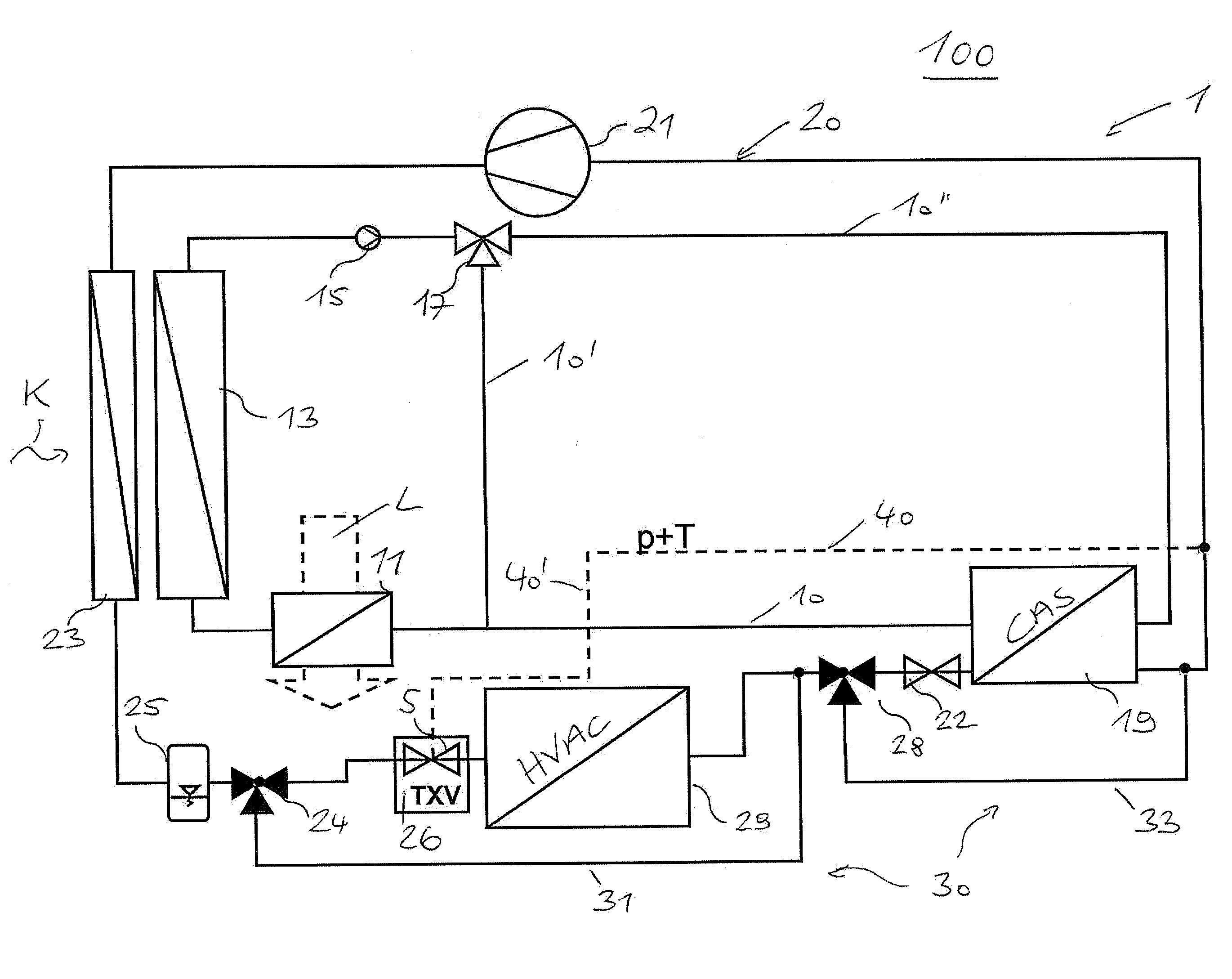
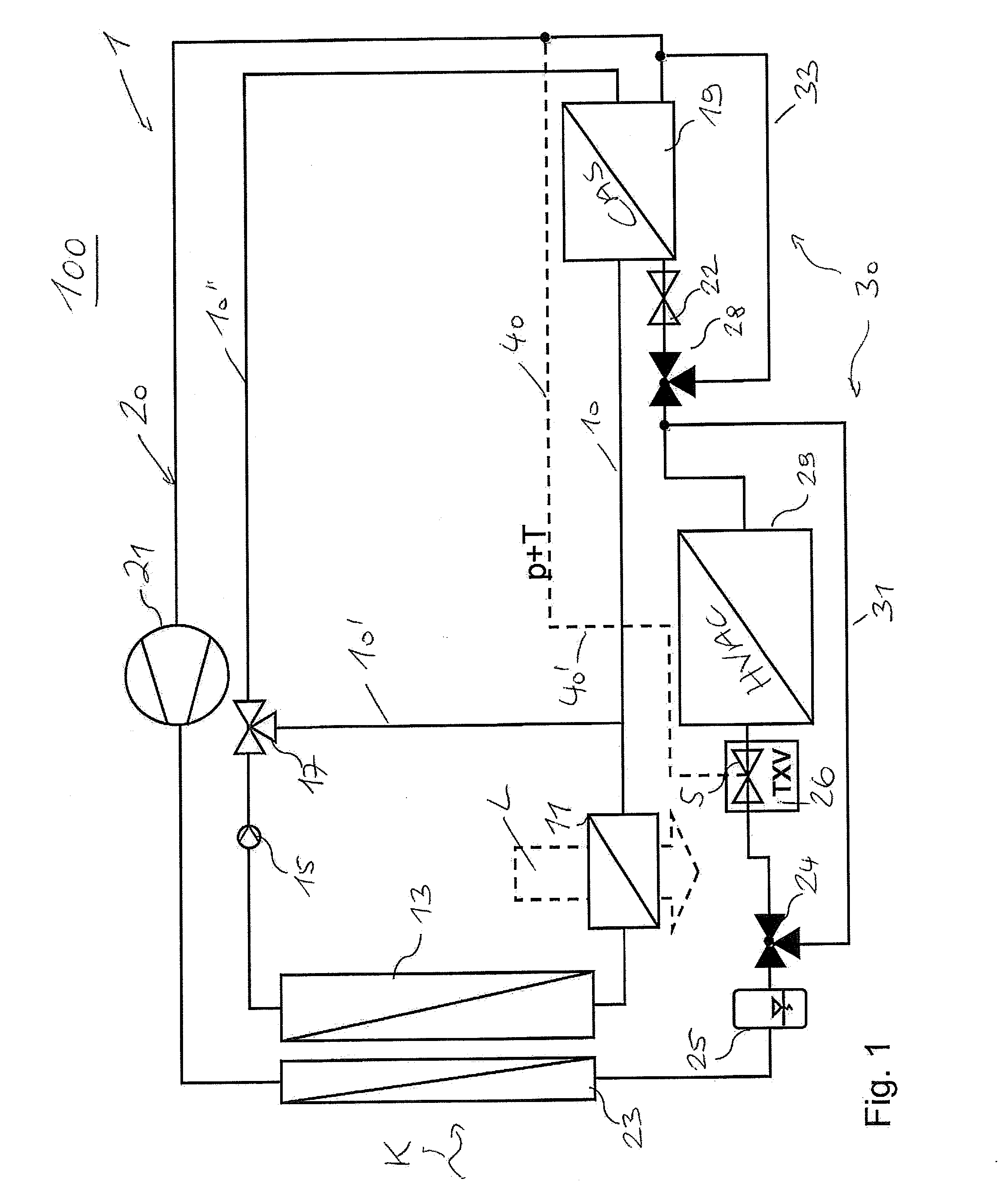
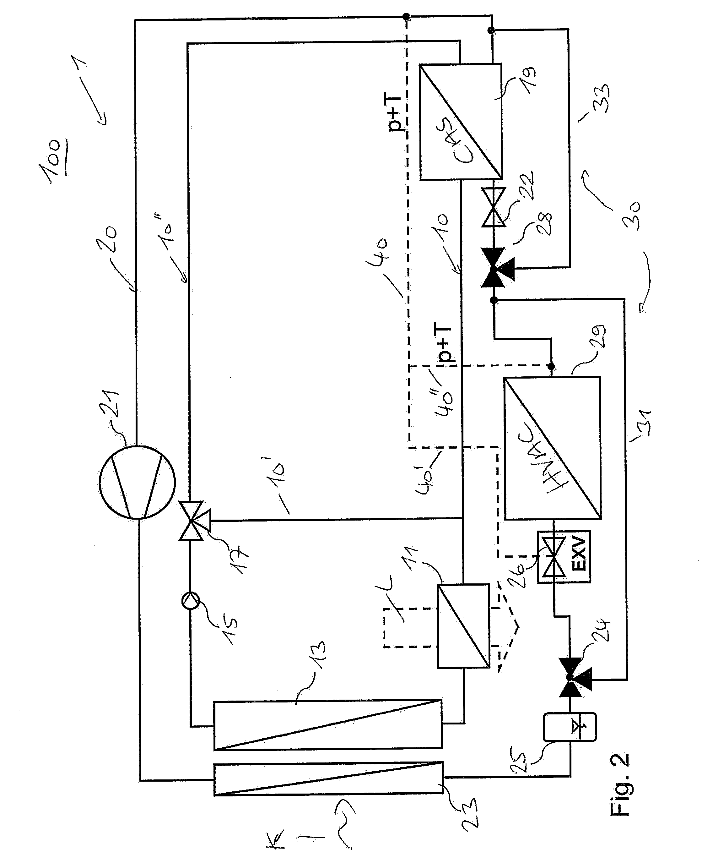
[0041]A circuit 100, represented symbolically in the present case, for charging an internal combustion engine, in particular a motor—preferably gasoline-fueled—with a charging fluid L has, according to the concept of the invention, a device 1 that is coupled through a heat exchanger 11 for the charging fluid L, and that is designed for cooling a coolant, which in turn is provided for cooling the charging fluid for charging the internal combustion engine. FIG. 1 through FIG. 3 show embodiments of the first variant, in which the first and second evaporators 29, 19 are connected in a series arrangement. FIG. 2 and FIG. 3 show additional variations of such a circuit 100, with a suitably modified device 1, wherein, for the sake of simplicity, the same reference symbols are used for identical parts or features, or parts or features having the same function. The charging fluid L can be understood to be, in particular, a substantially gaseous charging fluid—for example a charge air and / or a...


PUM


Abstract

A device for cooling a coolant, for cooling a charging fluid for charging an internal combustion engine is provided that includes a refrigerant guide, particularly a refrigerant circuit, and a coolant guide, particularly a coolant circuit; wherein the refrigerant guide comprises a first evaporator for a refrigerant for cooling an ambient air and a second evaporator for a refrigerant for cooling the coolant, the coolant guide comprises a heat exchanger for the charging fluid, a coolant cooler, and the second evaporator for the refrigerant of the refrigerant guide for cooling the coolant. In a first variant, the first and the second evaporator are disposed in series in the refrigerant guide. In a second variant, the first evaporator and the second evaporator are disposed in parallel in the refrigerant guide, particularly wherein a suction throttle is disposed downstream in the refrigerant flow after the second evaporator. A refrigerant bypass for the first and / or second evaporator serves for controlling the performance of the first and / or second evaporator.

Description

[0001]This nonprovisional application is a continuation of International Application No. PCT / EP2009 / 003861, which was filed on May 29, 2009, and which claims priority to German Patent Application No. DE 10 2008 028 290.1, which was filed in Germany on Jun. 16, 2008, and which are both herein incorporated by reference.BACKGROUND OF THE INVENTION[0002]1. Field of the Invention[0003]The present invention relates to a device for cooling a coolant that is provided for cooling a charging fluid for charging an internal combustion engine, having a refrigerant path and a coolant path; wherein the refrigerant path has a first evaporator for a refrigerant for cooling an ambient air and has a second evaporator for a refrigerant for cooling the coolant; the coolant path has a heat exchanger for the charging fluid, a radiator, and the second evaporator for a refrigerant of the refrigerant path for cooling the coolant. The invention further concerns a circuit for charging an internal combustion en...

Claims


Application Information

Patent Timeline
Patent Type & Authority Applications(United States)
IPC IPC(8): F02B29/04F25B41/00F25B41/04
CPCF02B29/0412Y02T10/146F02B29/0443Y02T10/12
Inventor WEINBRENNER, MARCUSKEMLE, ANDREASKUNBERGER, OTTOKARSTRAUSS, THOMASSCHAFER, BERND
Owner BEHR GMBH & CO KG
Learn More