System and method for heating feedwater using a solar heating system

a solar heating system and feedwater technology, applied in the field of solar heating systems to heat feedwater, can solve the problems of increasing the cost of solar technology to the site of turbomachine, reducing the output of the power plant, etc., and achieve the effect of increasing the overall efficiency of the power plant and reducing the amount of work

Inactive Publication Date: 2011-06-23
GENERAL ELECTRIC CO
View PDF4 Cites 4 Cited by
  • Summary
  • Abstract
  • Description
  • Claims
  • Application Information

AI Technical Summary

Benefits of technology

[0006]In accordance with an alternate embodiment of the present invention, a powerplant configured for increasing a temperature of a feedwater, the powerplant comprising: a steam turbine configured for converting steam into mechanical energy; a condensor integrated with the steam turbine, wherein the condensor is configured for transferring the steam discharged from the steam turbine into feedwater; a solar heating system configured for heating the feedwater, wherein the solar heating system receives the feedwater discharged from the condensor; wherein the solar heating system heats the feedwater from a first temperature to a second temperature; and a boiler configured for converting the feedwater to steam, wherein the boiler receives the feedwater, at the second temperature, which is discharged by the solar heating system, and wherein the boiler discharges the steam to the steam turbine; wherein the solar heating system reduces an amount of work performed by the boiler in heating the feedwater to a temperature allowing for conversion of the feedwater to steam; increasing an overall efficiency of a powerplant.

Problems solved by technology

Both of these approaches to heating the feedwater reduce the output of the powerplant.
This variance can make the addition of solar technology to a turbomachine site cost prohibitive.

Method used


Image

  • System and method for heating feedwater using a solar heating system
  • System and method for heating feedwater using a solar heating system
  • System and method for heating feedwater using a solar heating system

Examples


first embodiment

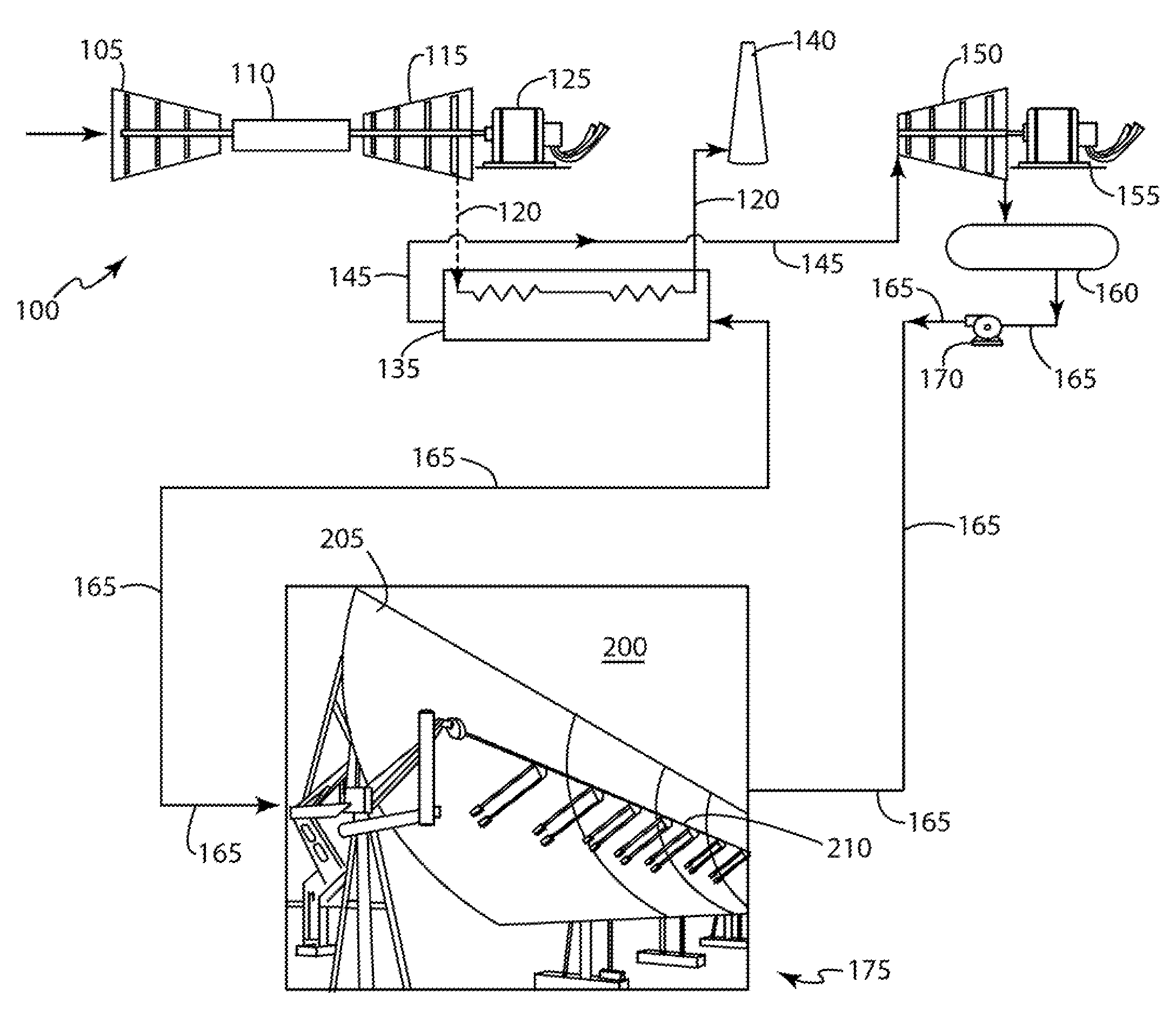
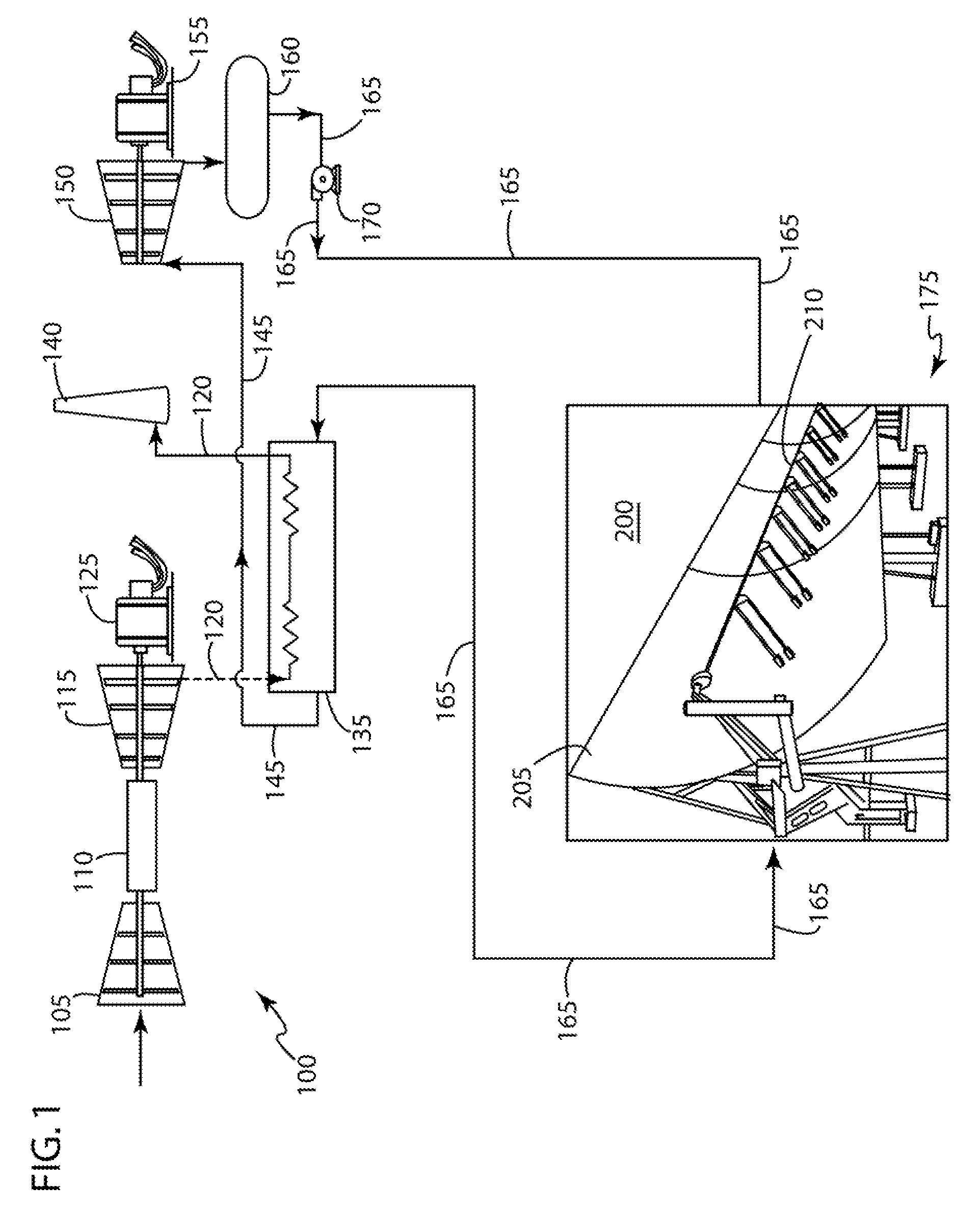
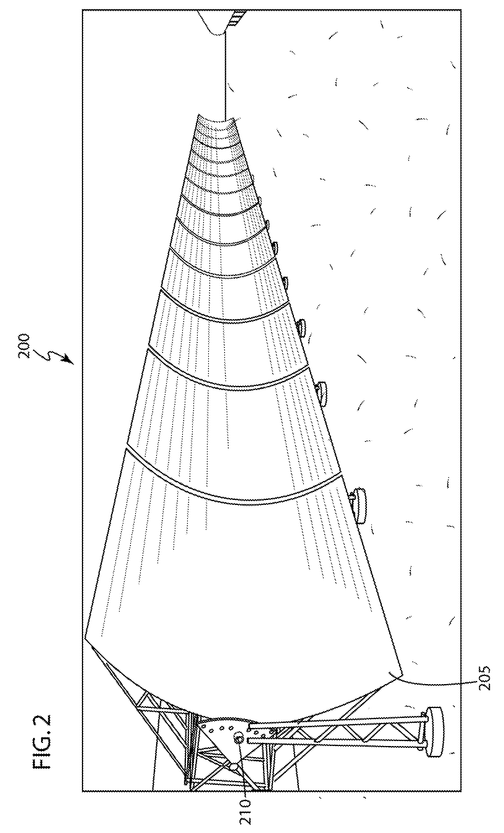
[0024]the a solar heating system 175 may comprise a parabolic trough system 200, as illustrated in FIGS. 1 and 2. An embodiment of the parabolic trough system 200 may comprise a plurality of linear parabolic reflectors 205 that concentrate the sunlight onto a receiver 210 positioned along a focal line of the parabolic reflectors 205. The linear parabolic reflectors 205 are designed to follow the sunlight during the daylight hours by tracking along at least one axis (not illustrated in the FIGS.). The receiver 210 may comprise a pipe through which the feedwater 165 may flow. Here, the solar heating system 175 may heat the feedwater 165 via a convection form of heat transfer, such as, but not limiting of, forced convection, natural convection, or the like.

second embodiment

[0025]the solar heating system 175 may comprise a solar tower system 300, as illustrated in FIG. 3. An embodiment of the solar tower system 300 may incorporate a plurality of tracking reflectors 305 for concentrating sunlight light onto a central receiver 310 near the top of a tower 315. The receiver 310 may comprise a pipe through which the feedwater 165 may flow. Here, the solar heating system 175 may heat the feedwater 165 via a convection form of heat transfer, such as, but not limiting of, forced convection, natural convection, or the like.

[0026]In use, the at least one solar heating system 175 may heat the feedwater 165 from a first temperature to a second temperature. Here, the first temperature may be considered the temperature of the feedwater 165 existing the condensor 160. In an embodiment of the present invention, the first temperature may be up to about 150 degrees Fahrenheit. Furthermore, the second temperature may be considered the heated temperature of the feedwater ...


PUM


Abstract

An embodiment of the present invention may take the form of a system and method that may use at least at least one solar heating system to heat the feedwater consumed by a boiler. An embodiment of the present invention may incorporate concentrated solar power (CSP). Generally, CSP systems incorporate a plurality of lenses, mirrors, or combinations thereof and a tracking system to focus a large area of sunlight forming a small concentrated beam of light. The concentrated light may then be used as a heat source. In an embodiment of the present invention, the heat source may be used to partially or completely heat the feedwater consumed by a boiler. CSP systems may take the form of a solar trough system, a parabolic dish system, a solar power tower system, or the like.

Description

BACKGROUND OF THE INVENTION[0001]The present invention relates to the feedwater consumed by a boiler during operation or a steam turbine; and more particularly to a system and method of incorporating a solar heating system to heat the feedwater.[0002]A powerplant incorporating a steam turbine is typically integrated with a condensor and a boiler. The condensor receives the low energy steam, or steam-water mixture, discharged by the steam turbine. After receiving the low energy steam, the condensor extract heat from the steam, which condenses to form feedwater. The boiler receives and heats the feedwater until conversion to steam, which is sent to the steam turbine, and this closed loop process is repeated. Some boilers, such as, but not limiting of, a heat recovery steam generator (HRSG) heat the feedwater with energy from the exhaust of a gas turbine. Other boilers heat the feedwater via steam extracted from the steam turbine. Both of these approaches to heating the feedwater reduc...

Claims


Application Information

Patent Timeline
Patent Type & Authority Applications(United States)
IPC IPC(8): F01K27/00F22D1/00F24J2/00F24S23/00F24S23/74
CPCY02E10/46Y02E10/45F24J2/07F03G6/065F24J2/14F24S20/20F24S23/74Y02E10/40
Inventor BOSS, MICHAEL J.
Owner GENERAL ELECTRIC CO
Why Eureka
Try Eureka