Bi-directional cascade heat pump system

a cascade heat pump and cascade technology, applied in heat pumps, heating types, domestic cooling apparatus, etc., can solve the problems of limited operating modes, need for reversible refrigerant circuits, and so as to avoid unnecessary mixing of relatively high and low temperature fluids

Active Publication Date: 2011-06-23
TRANE INT INC
View PDF34 Cites 35 Cited by
  • Summary
  • Abstract
  • Description
  • Claims
  • Application Information

AI Technical Summary

Benefits of technology

[0006]It is an object of some embodiments of the invention to provide a heat pump system that avoids unnecessary mixing of relatively high and low temperature fluid.
[0007]Another object of some embodiments is to provide a wide selection of heating and / or cooling modes without having to reverse the refrigerant flow through a refrigerant circuit.
[0008]Another object of some embodiments is to provide a wide selection of heating and / or cooling modes without having to switch the operation of a heat exchanger between condensing and evaporating.

Problems solved by technology

Drawbacks of current geothermal heat pumps include limited operating modes, need for reversible refrigerant circuits, need for selectively operating a heat exchanger as a condenser and an evaporator, and / or unnecessary mixing of relatively high and low temperature fluid.

Method used


Image

  • Bi-directional cascade heat pump system
  • Bi-directional cascade heat pump system
  • Bi-directional cascade heat pump system

Examples


Embodiment Construction

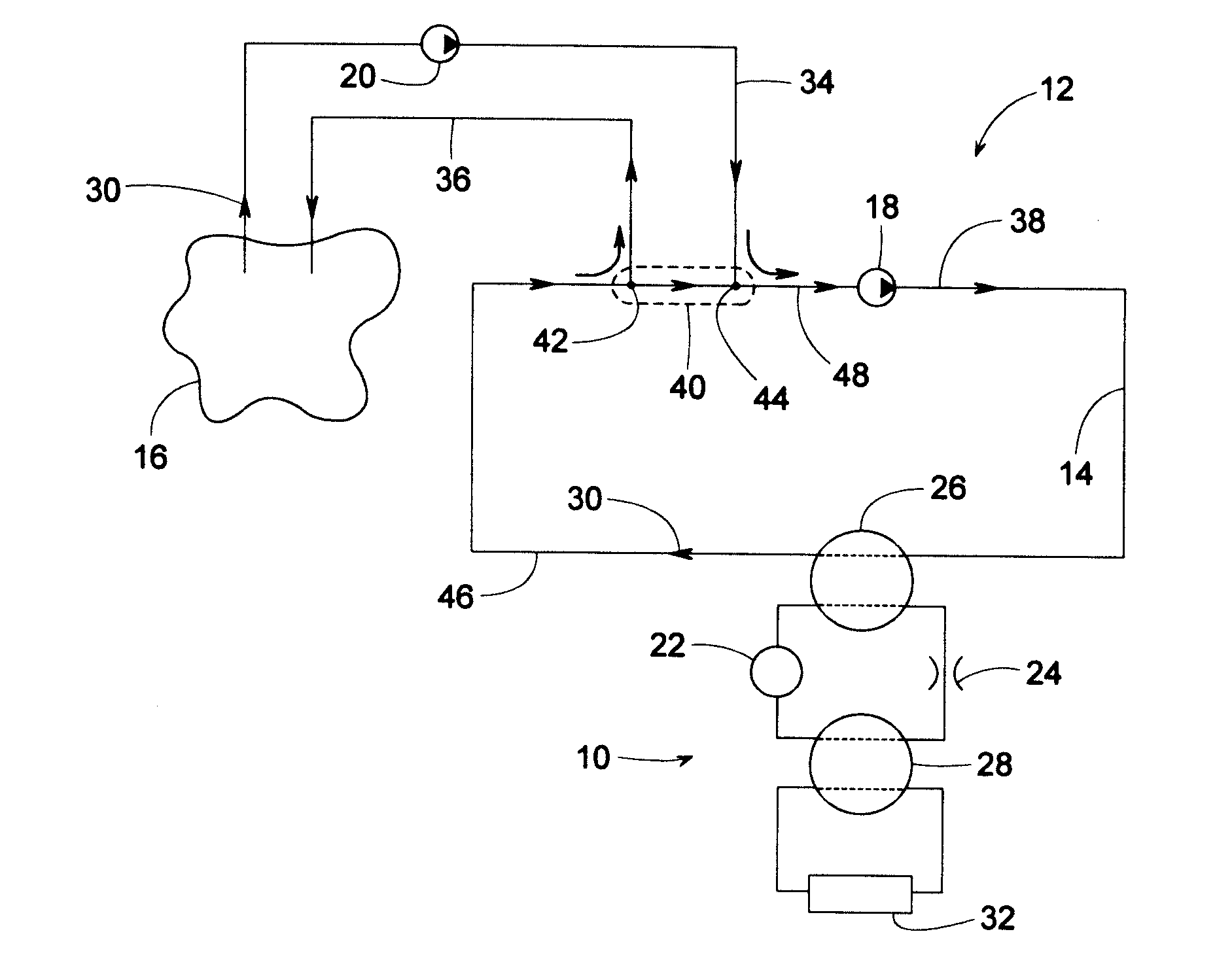
[0032]FIG. 1 schematically illustrates a heat pump system 12 comprising a chiller 10, a fluid circulation loop 14, a secondary fluid source 16, a fluid circulation pump 18, and a secondary fluid pump 20. The term, “chiller” refers to any refrigerant circuit comprising a refrigerant compressor (e.g., centrifugal compressor, screw compressor, reciprocating compressor, scroll compressor, etc.), two heat exchangers (a condenser and an evaporator) and a flow restriction (e.g., expansion valve, orifice, capillary, etc.). Chiller 10, for example, includes a compressor 22, a flow restriction 24, and heat exchangers 26 and 28, wherein one heat exchanger functions as an evaporator and the other as a condenser.

[0033]With the refrigerant in heat exchanger 26 being in heat transfer relationship with a secondary fluid 30 (e.g., water, glycol, air, and combinations thereof) in loop 14, chiller 10 serves to effectively “pump” heat between fluid source 16 and some desired heating or cooling load 32 ...


PUM


Abstract

A multi-mode, bi-directional cascade heat pump system, according to some examples, includes at least two chillers each being part of a unidirectional refrigerant circuit. The system includes heat exchangers each of which are dedicated to operate as just a condenser or as just an evaporator, regardless of the system's operating mode. In some modes, a secondary fluid transfers heat between the condenser of one chiller and the evaporator of another chiller before the fluid returns to a secondary fluid source such as, for example, a geothermal borefield or a conventional water source. In some embodiments, fluid is withdrawn from a borefield by way of a pump having a speed that varies to maintain a desired fluid temperature and / or a desired heat transfer rate at the borefield. The heat pump system includes means for minimizing flow through the borefield and for minimizing unnecessary mixing of relatively high and low temperature fluid.

Description

BACKGROUND OF THE INVENTION[0001]1. Field of the Invention[0002]The subject invention generally pertains to refrigerant systems and more specifically to a cascade heat pump system.[0003]2. Description of Related Art[0004]Geothermal heat pump systems often include a refrigerant system that exchanges heat with the ground via a borefield or some other means. A borefield basically is a buried network of pipes through which a fluid is pumped. As the fluid flows through the borefield, the fluid exchanges heat with the surrounding ground, and the refrigerant system then uses the exchanged heat energy to help heat or cool a certain load.[0005]Drawbacks of current geothermal heat pumps include limited operating modes, need for reversible refrigerant circuits, need for selectively operating a heat exchanger as a condenser and an evaporator, and / or unnecessary mixing of relatively high and low temperature fluid. Consequently, there is a need for a better heat pump system that is particularly u...

Claims


Application Information

Patent Timeline
Patent Type & Authority Applications(United States)
IPC IPC(8): F25B27/00F25D31/00F25B13/00
CPCF25B7/00F25B2400/06F25B30/06F25B29/003Y02B10/40F24F5/0046F24F2005/0057F25B49/02F25B2313/002F25B2600/13F25B2700/21
Inventor CLINE, LEE R.SCHWEDLER, MICHAEL C. A.HANSON, SUSANNA S.FIEGEN, BRIAN J.
Owner TRANE INT INC
Why Eureka
Try Eureka