
Motor and electric parking brake system

a technology of parking brake and motor, which is applied in the direction of braking system, electric vehicles, dynamo-electric machines, etc., can solve the problems of motor and epb system malfunction, dangerous to drive a car with a malfunctioning epb system, etc., and achieve the effect of reducing the output speed of the motor

Active Publication Date: 2011-06-23
JOHNSON ELECTRIC SA
View PDF14 Cites 14 Cited by
  • Summary
  • Abstract
  • Description
  • Claims
  • Application Information

AI Technical Summary

Benefits of technology

[0013]According to a second aspect, the present invention also provides an electric parking brake system, comprising: an electronic control unit; a motor controlled by the electronic control unit; a gearbox for reducing the output speed of the motor; and brake members driven by the gearbox for locking wheels; wherein the motor is a motor as defined above.

Problems solved by technology

The motor as well as the EPB system will malfunction.
It is dangerous to drive a car having a malfunctioning EPB system.

Method used


Image

  • Motor and electric parking brake system
  • Motor and electric parking brake system
  • Motor and electric parking brake system

Examples


Embodiment Construction

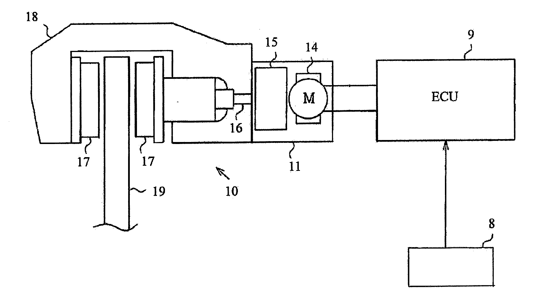
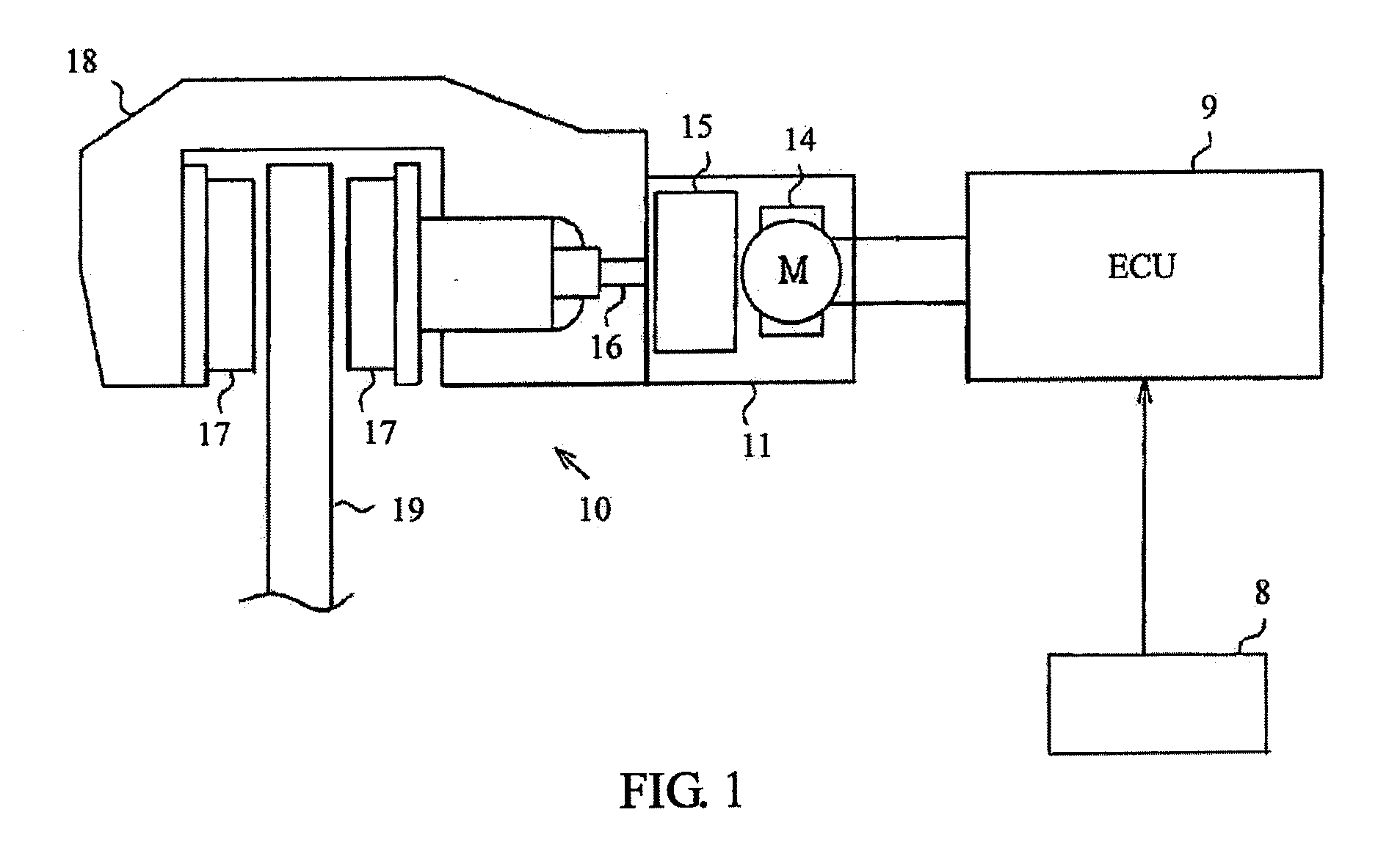
[0021]As shown in FIG. 1, an EPB system according to the preferred embodiment of the present invention comprises sensors 8, an electronic control unit (ECU) 9 and a brake section 10 controlled by the ECU 9. The sensors 8 are connected to the ECU 9 and detect movement of a vehicle and delivers a corresponding signal to the ECU 9.

[0022]The brake section 10 comprises a driving apparatus 11, braking members such as a pair of brake pads 17, driven by the driving apparatus 11 and a support member, such as a caliper 18, fixed to a non-rotating part of the vehicle. The driving apparatus 11 and the brake pads 17 are connected to the caliper 18. A brake disc or rotor 19 that spins with one of the vehicle wheels (not shown) is disposed between the pair of brake pads. The brake pads are moved by one or more pistons of the caliper to squeeze the brake disc to grip or slow the rotation of the disc which in turn holds the vehicle stationary or slows movement of the vehicle. The piston or pistons o...


PUM


Abstract

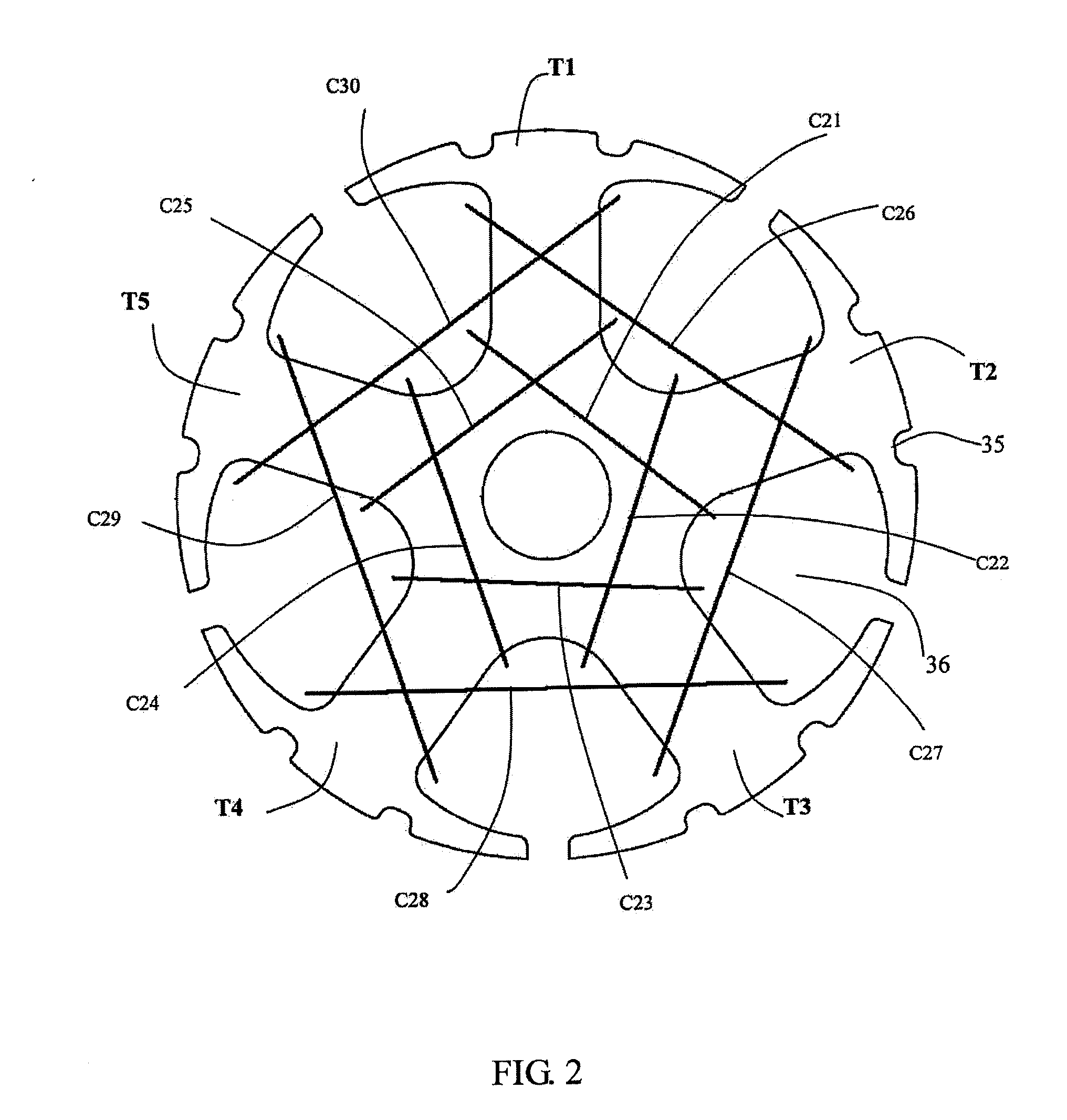
A motor for actuating brake members of an electric parking (EPB) system, comprises a stator and a rotor rotatably mounted to the stator. The rotor comprises a shaft, a commutator, a rotor core fixed to the shaft, and rotor windings wound about teeth of the rotor core and electrically connected to segments of the commutator. The rotor windings comprise a plurality of winding units, each of the wining units comprising at least two coils. The coils of each winding unit are wound about the same teeth and connected to a same pair of segments.

Description

CROSS REFERENCE TO RELATED APPLICATIONS[0001]This non-provisional patent application claims priority under 35 U.S.C. §119(a) from Patent Application No. 200910109741.2 filed in The People's Republic of China on Nov. 17, 2009, the entire contents of which are fully incorporated herein by reference.FIELD OF THE INVENTION[0002]This invention relates to an electric parking brake system and to a DC motor for an electric parking brake system.BACKGROUND OF THE INVENTION[0003]Service brake systems and parking brake systems are two kinds of brake systems widely used in vehicles. A service brake system is a braking system used to slow or stop a moving vehicle, while a parking brake system is used to prevent a stationary vehicle from moving or rolling away. Traditional parking brake systems were manually hand operated and are also called ‘handbrakes’. A driver needed to pull up the handbrake manually to prevent a stationary vehicle from rolling away and needed to manually release the handbrake...

Claims


Application Information

Patent Timeline
Patent Type & Authority Applications(United States)
IPC IPC(8): B60T13/74H02K3/28
CPCB60T13/741H02K2201/06H02K23/26H02K3/28
Inventor MA, HANG CHEONGCHUNG, HING SHINGLIAO, HAI NING
Owner JOHNSON ELECTRIC SA
Learn More