Pinch manifold

a technology of non-contact fluid and manifold, which is applied in the direction of diaphragm valves, instruments, engine diaphragms, etc., can solve the problems of unreliable operation and automation control of solenoid pinch valves, corroding effects on machine parts, and minimally-interactive devices

Inactive Publication Date: 2011-06-23
UNIV OF MIAMI
View PDF3 Cites 6 Cited by
  • Summary
  • Abstract
  • Description
  • Claims
  • Application Information

AI Technical Summary

Benefits of technology

[0007]The present invention advantageously provides a substance delivery control system that is scalable, cost-effective, reduces the complexities and numbers of components, is not susceptible to failures from power interruption, and further reduces the amount of electrical power required for operation.
[0013]The present invention also provides a method of controlling the passage of a substance through a conduit, including aligning a first circumferential segment of a first delivery control element, a second circumferential segment of a second delivery control element, and a first compression element, where the alignment of the first and second circumferential segments with the first compression element allows the passage of a substance through a first conduit adjacent the first compression element; misaligning the first and second circumferential segments, where the misalignment causes the first compression element to restrict the passage of the substance through the first conduit; and aligning the first circumferential segment, the second circumferential segment, and a second compression element, where the alignment of the first and second circumferential segments with the second compression element allows the passage of a substance through a second conduit adjacent the second compression element. The misalignment may be accomplished at least in part by rotating the first circumferential segment a first predefined range independently of the second circumferential segment, and the alignment of the first and second circumferential segments with the second compression element may be achieved at least in part by rotating the first and second circumferential segments together in a first direction, and then rotating the first circumferential segment independently of the second circumferential segment in a second direction. The method may further include partially compressing or obstructing the conduit, for example by partial rotation of the first disk to accurately control the percentage or degree of compression of the selected conduit.

Problems solved by technology

The use of such minimally-interactive devices is also widespread in the food and beverage industry where sterility of fluids and / or their corroding affects on machine parts also pose a concern.
In applications involving the management of a variety of fluids or conduits at the same time, the operation and automated control of solenoid pinch-valves can be problematic and unreliable.
For example, non-contact fluid manifolds with automated controls using electrical pinch-valves controlled by solenoids to regulate fluid flow are complex and prone to failure.
A prevalent problem occurs when electric current through a solenoid is interrupted, resulting in the electrically-induced closed or open-state of the valve being compromised.
Such a failure may result in the unintended dispensing, mixing, or movement of the substances being handled, leading to losses of time and materials, compromising safety and efficiency, and creating potentially hazardous conditions.
Other approaches involve complex cam arrangements and require at least two active elements (a motor and a solenoid) to function, and may entail a significant number of mechanical elements.
Moreover, as the solenoids must also draw electrical current in addition to the motor, the overall power consumption of such a system may be undesirably high.
Further, such designs are only cost effective when a large number of equivalent individual pinch valves are needed, making it difficult and costly to scale down or otherwise adapt the typical system to particularized applications.

Method used


Image

  • Pinch manifold
  • Pinch manifold
  • Pinch manifold

Examples


Embodiment Construction

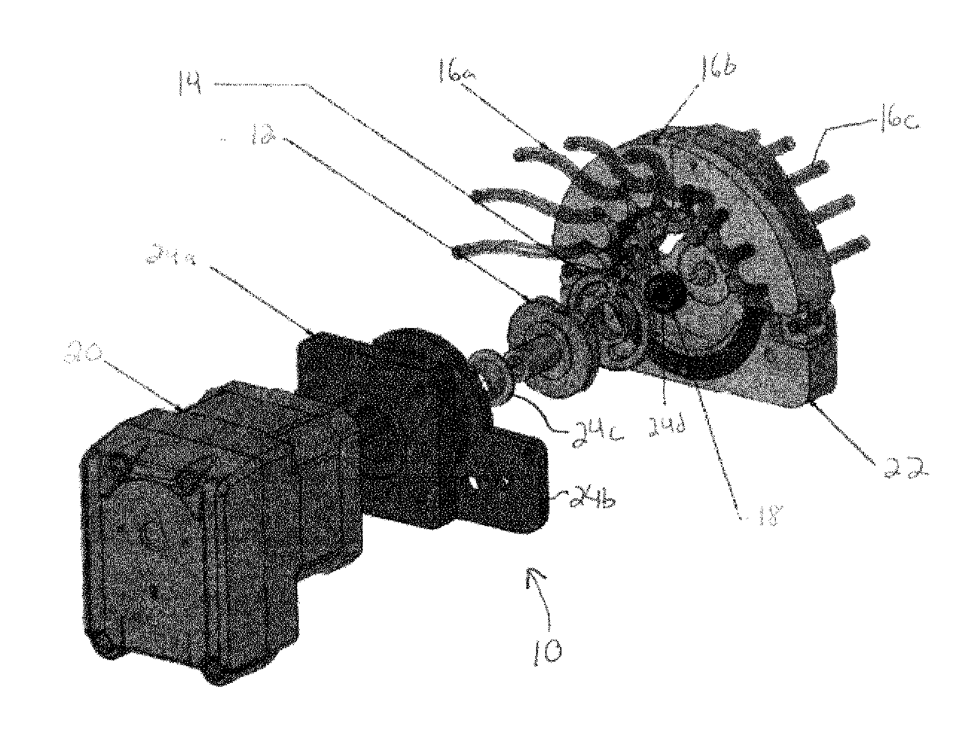
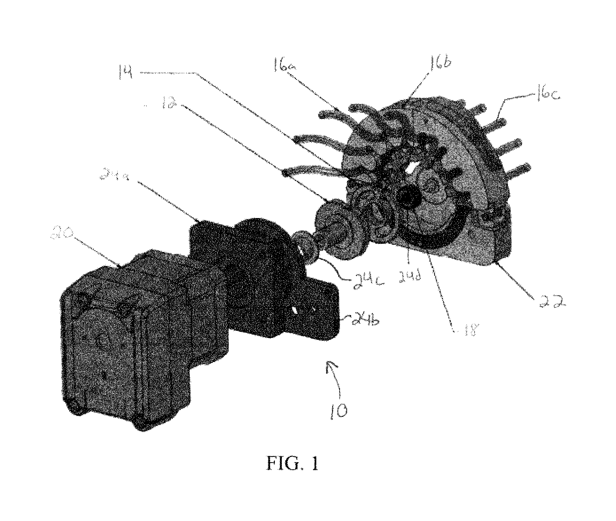
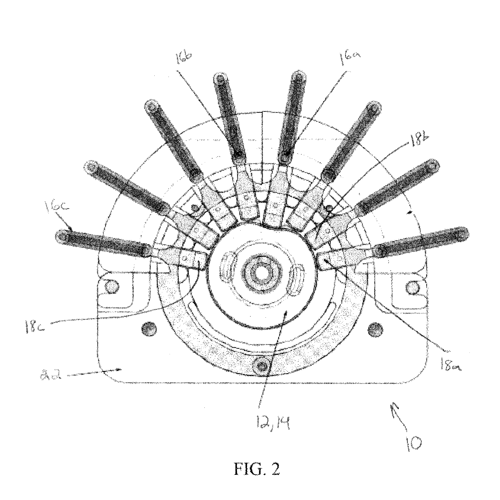
[0022]The present invention advantageously provides a substance delivery control system that is scalable, cost-effective, reduces the complexities and numbers of components, is not susceptible to failures from power interruption, and further reduces the amount of electrical power required for operation. Now referring to the figures, there is shown in FIGS. 1-3 an embodiment of a substance delivery control system 10 constructed in accordance with the principles of the present invention. In particular, the substance delivery control system 10 may generally include a plurality of delivery control elements, such as a first delivery control element 12 and a second delivery control element 14, movable with respect to one another to open, close, or otherwise affect one or more conduits 16 and thus the flow or movement of a substance therethrough. The system may also include one or more compression elements 18 interacting with the delivery control elements to compress or otherwise engage th...


PUM


Abstract

The present invention includes substance delivery control system having a first conduit defining a lumen for the passage of a substance therethrough; a first delivery control element defining a first conduit state selection element; a second delivery control element defining a second conduit state selection element, where the alignment of the first and second conduit state selection elements places the conduit in a first state, and where misalignment of the first and second conduit state selection elements places the conduit in a second state.

Description

FIELD OF THE INVENTION[0001]The present invention relates to a method and system for selecting and regulating fluid flow through one or more conduits, and in particular, a non-contact fluid control device.BACKGROUND OF THE INVENTION[0002]Many medical and industrial applications involve handling or otherwise processing hazardous, sterile, or toxic fluids or substances that could damage machine components or result in the contamination of the substance being handled. For example, reduced or no-contact devices are largely used in biological / chemical fluid processing to prevent the unwanted interaction between processing components and the fluids themselves. The use of such minimally-interactive devices is also widespread in the food and beverage industry where sterility of fluids and / or their corroding affects on machine parts also pose a concern.[0003]Devices typically used in such situations include non-contact valves, with the solenoid pinch-valve being the most common. A pinch valv...

Claims


Application Information

Patent Timeline
Patent Type & Authority Applications(United States)
IPC IPC(8): B67D7/06
CPCF16K11/027F16K7/065Y10T137/86445
Inventor BERNAL, ANDRESPOO, FAUSTINO
Owner UNIV OF MIAMI
Why Eureka
Try Eureka