
Reversible seat belt tensioner

a seat belt tensioner and reversible technology, which is applied to belt retractors, vehicle safety belts, vehicle components, etc., can solve the problems that the vehicle manufacturers no longer tolerate the arrangement of components with respect to each other, and the noise of the crown gear unit and the worm gear unit during the seat belt tensioning, in particular for vehicles of the higher quality class, can not be freely chosen, and achieve the effect of reducing noise and compact configuration

Active Publication Date: 2011-06-23
AUTOLIV DEV AB
View PDF4 Cites 5 Cited by
  • Summary
  • Abstract
  • Description
  • Claims
  • Application Information

AI Technical Summary

Benefits of technology

[0005]It is the object of the invention to provide a reversible seat belt tensioner wherein the electric motor, the belt shaft with the drive wheel and the drive shaft can even be arranged in different orientations with respect to each other so that the reversible seat belt tensioner can have an overall more compact configuration and can even be arranged in cramped installation spaces. Moreover, the noises developing during the belt tensioning shall be reduced.
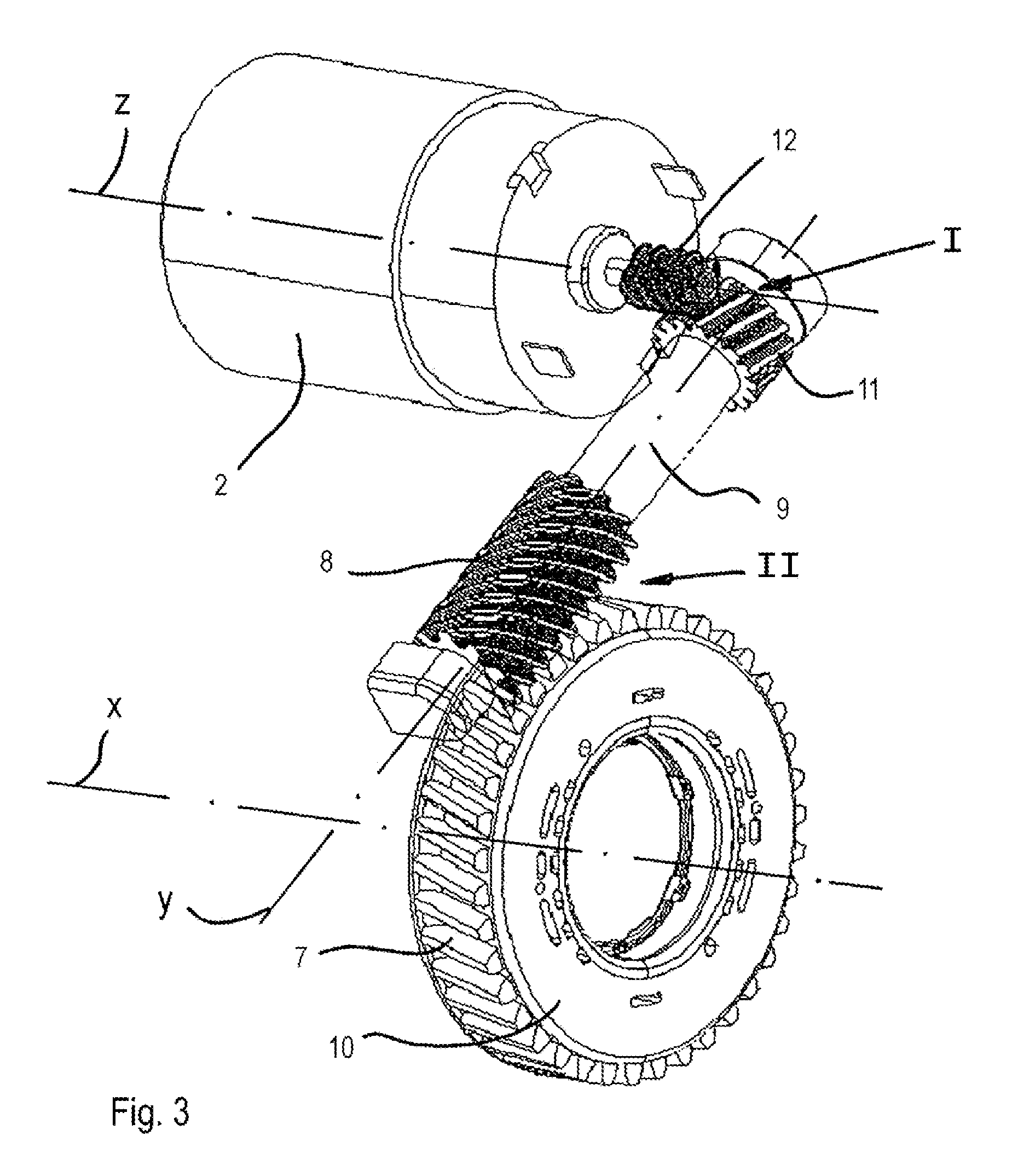
[0006]The solution of the object according to the invention is that the drive shaft is connected to the drive wheel and / or to the electric motor via a helical gear unit. The use of a helical gear unit provides the advantage that the rotational axes of the meshing components can also be arranged at angles not equal to 90 degrees with respect to each other. Thereby, the components can be arranged at any angle with respect to each other so that the arrangement can be carried out in the sense of a compact configuration and utilization of the available free spaces. As the components in the helical gear units only come into punctiform contact, in addition, the noise development is substantially reduced. Helical gear units are generally distinctly known for the fact that helical gears with different helix angles but an equal pitch and the same engagement angle are coupled. The axles can thereby cross at any angle owing to different helix angles. Furthermore, a helical gear unit provides the advantage that the helical gears, in addition to the diameter ratios, by means of the choice of the helix angles provide an additional possibility to change the transmission ratio. Moreover, the helical gears of the helical gear unit can be displaced axially without the helical gears losing engagement. Thereby, the production accuracy requirements are substantially reduced so that the effort and the costs for fulfilling the required production accuracy requirements are substantially reduced.

Problems solved by technology

A disadvantage in this embodiment is that the arrangement of the components with respect to each other cannot be freely chosen, as the gear wheels of the gear units deflect the rotational movement by 90 degrees each, and, therefore, the rotational axes of the meshing rotating components have to be arranged at an angle of 90 degrees with respect to each other.
It has further turned out that the noises developing in the crown gear unit and in the worm gear unit during the seat belt tensioning, in particular for vehicles of the higher quality class, are no longer tolerated by the vehicle manufacturers.

Method used


Image

  • Reversible seat belt tensioner
  • Reversible seat belt tensioner
  • Reversible seat belt tensioner

Examples


Embodiment Construction

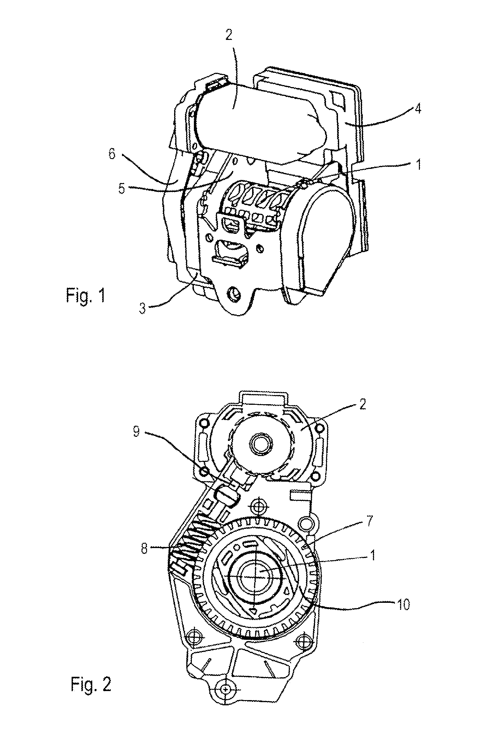
[0014]FIG. 1 shows a reversible seat belt tensioner comprising a seat belt retractor 1 and an electric motor 2 driving the seat belt retractor 1 in the belt winding direction during the reversible tensioning. On the side of the reversible seat belt tensioner, an electronic control unit 4 (ECU) actuating the electric motor 2 is arranged. Furthermore, on the front end of the seat belt retractor housing 5, a gear unit housing 3 comprising a corresponding covering 6 is arranged in which gear unit housing the later described drive shaft along with the associated gear units and the drive wheel for coupling the electric motor 2 to the belt shaft 1 is arranged.

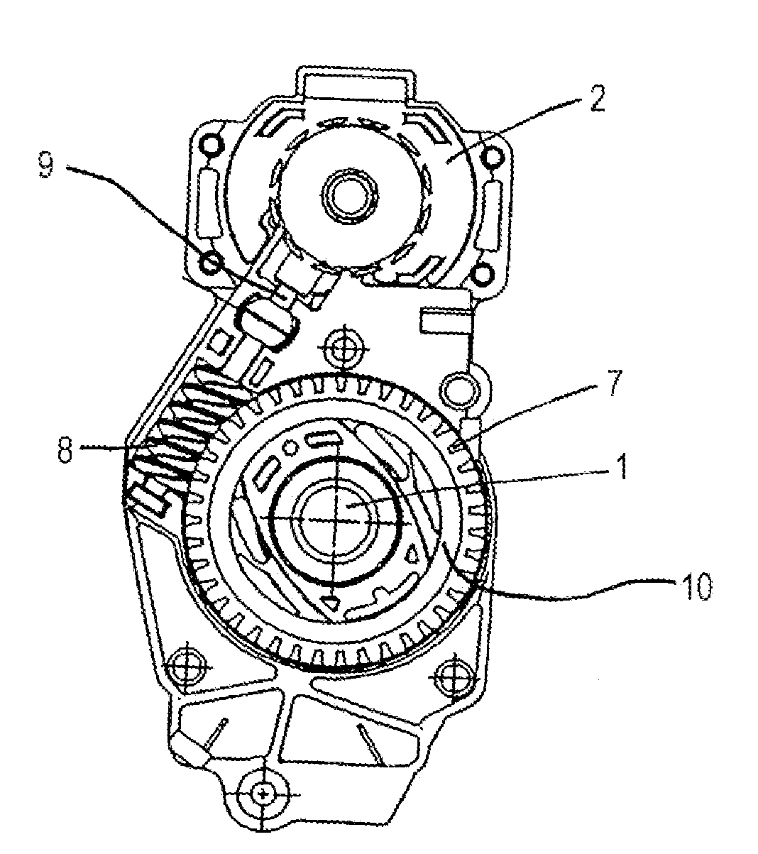
[0015]FIG. 2 shows the same reversible seat belt tensioner from the gear unit-side, however without covering 6. Between the belt shaft 1 and the electric motor 2 a drive shaft 9 engaging with a gearing 7 of a drive wheel 10 via a gearing 8 can be seen. The connection between the electric motor 2 and the drive shaft 9 is not shown, but...


PUM


Abstract

A reversible seat belt tensioner includes an electric motor (2), a belt shaft (1) drivable in the belt winding direction by the electric motor (2) via a drive wheel (10), and a drive shaft (9) transmitting the rotational movement of the electric motor (2) to the drive wheel (10). The drive shaft (9) is connected to at least one of the drive wheel (10) and the electric motor (2) via a helical gear unit. The use of a helical gear unit provides the advantage that the rotational axes of the meshing components can be arranged at angles other than 90 degrees with respect to each other because the components in the helical gear units only come into punctiform contact.

Description

CROSS REFERENCE TO RELATED APPLICATIONS[0001]This application claims priority to German Patent Application 10 2008 048 339.7, filed Sep. 22, 2008, and International Patent Application No. PCT / EP2009 / 006287, filed Aug. 31, 2009.TECHNICAL FIELD OF THE INVENTION[0002]The invention relates to a reversible seat belt tensioner comprising an electric motor, a belt shaft drivable in the belt winding direction by the electric motor via a drive wheel, and a drive shaft transmitting the rotational movement of the electric motor to the drive wheel.BACKGROUND OF THE INVENTION[0003]From WO 2003 / 099619 A2, a reversible seat belt tensioner is known wherein the drive shaft transmitting the rotational movement of the electric motor to the belt shaft is coupled to the electric motor via a crown gear unit and is coupled to the drive wheel via a worm gear unit.[0004]A disadvantage in this embodiment is that the arrangement of the components with respect to each other cannot be freely chosen, as the gear...

Claims


Application Information

Patent Timeline
Patent Type & Authority Applications(United States)
IPC IPC(8): B60R22/46B65H75/48B60R22/34
CPCB60R2022/4666B60R22/46B60R22/34
Inventor LUCHT, ANDREASBORGWARD, MATTHIASBAUDINET, SEBASTIEN
Owner AUTOLIV DEV AB
Learn More