Vibration damping of a ceiling mount carrying a surgical microscope

Inactive Publication Date: 2011-06-23
LEICA MICROSYSTEMS (SCHWEIZ) AG
View PDF14 Cites 9 Cited by
  • Summary
  • Abstract
  • Description
  • Claims
  • Application Information

AI Technical Summary

Benefits of technology

[0012]It is an object of the present invention to overcome these disadvantages and to provide a ceiling mount which will efficiently suppress the above-mentioned vibrations, regar

Problems solved by technology

However, the complexity of construction and manufactu

Method used


Image

  • Vibration damping of a ceiling mount carrying a surgical microscope
  • Vibration damping of a ceiling mount carrying a surgical microscope
  • Vibration damping of a ceiling mount carrying a surgical microscope

Examples


Embodiment Construction

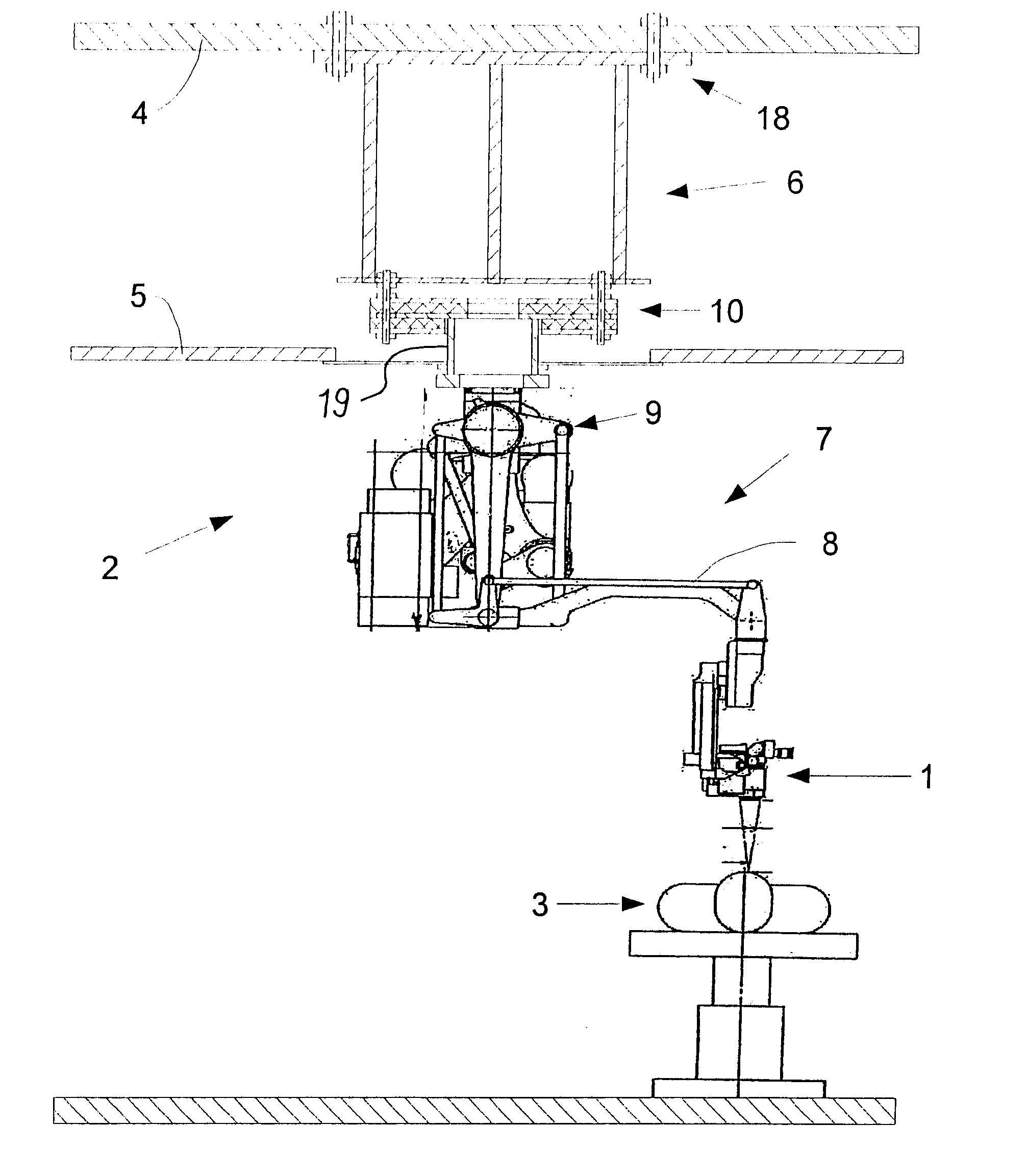
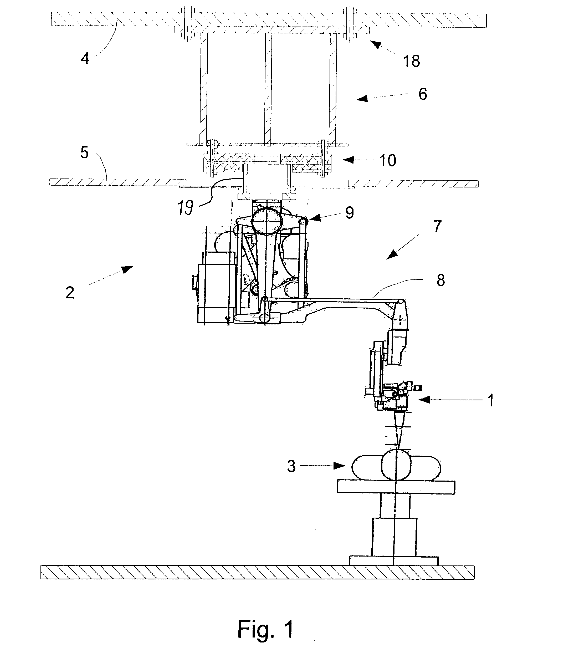
[0024]FIG. 1 shows a surgical microscope 1 suspended above a patient 3 from a ceiling mount 2. Ceiling mount 2 is attached to a ceiling 4 (steel, concrete, reinforced concrete, or the like). Also shown is an intermediate ceiling 5, which is optional. In the region of intermediate ceiling 5, or slightly thereabove or therebelow, ceiling mount 2 has an interface 10 which has a damping function and which decouples section 6 located thereabove from section 7 located therebelow. The mounting position of this interface is variable and depends, inter alia, on the length of the vertical portion of the stand. In lower section 7, there extends a multi-part support arm 8 carrying microscope 1 on its end. Also shown is an articulation mechanism 9 serving for the movement and mass-balancing of microscope 1.

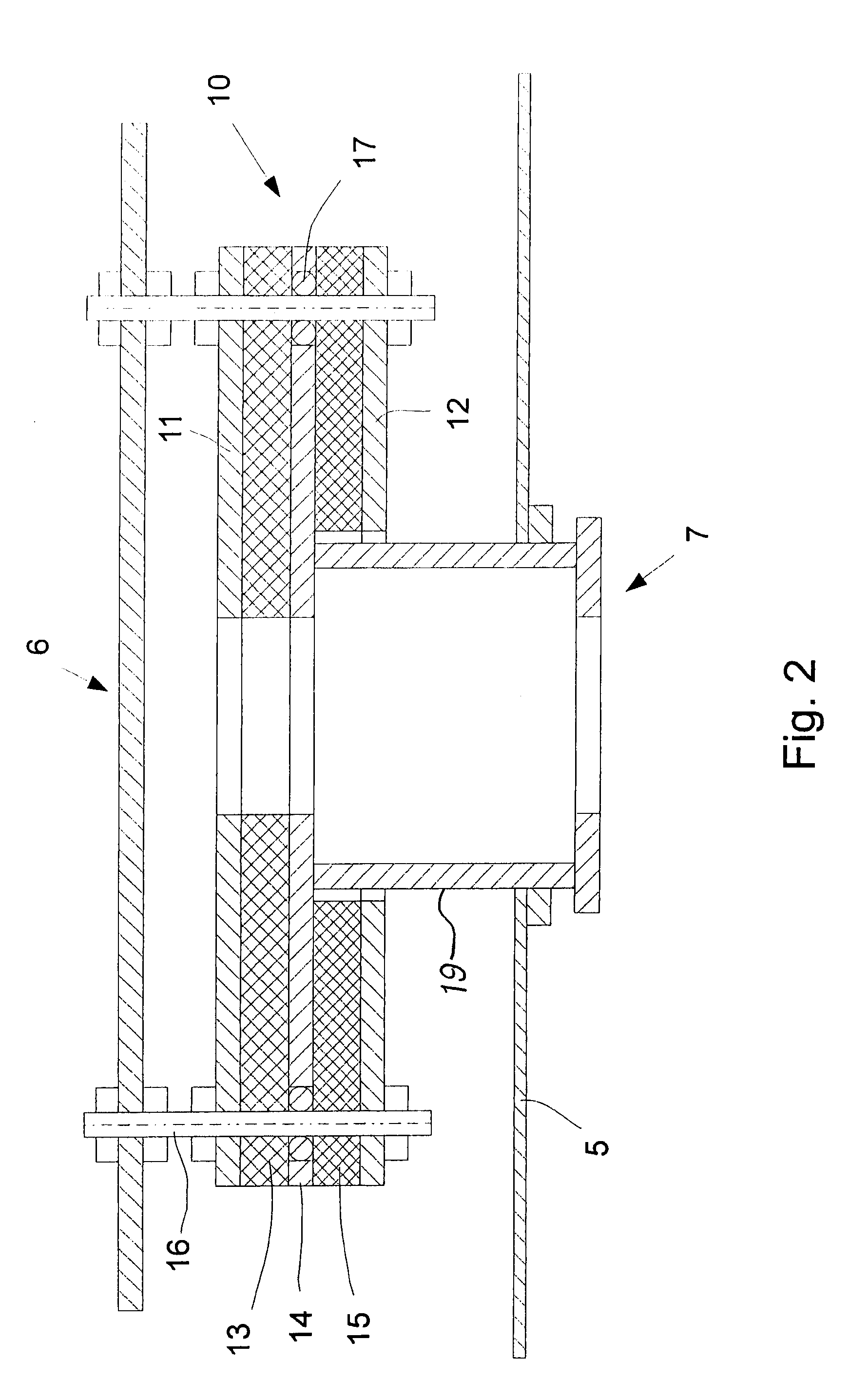
[0025]Damping interface 10, which is shown enlarged in FIG. 2, serves to rapidly damp or prevent the transmission of vibrations via the bracket plate to ceiling mount 2, regardless of the dire...


PUM


Abstract

The present invention relates to a ceiling mount for a surgical microscope, including at least two load-bearing sections joined together by a damping interface, said interface including at least two damping layers which are made of damping material and are separated from each other by a bracket plate made of non-damping material. In order to damp a wider spectrum of mechanical disturbances even more efficiently, the material of one damping layer has other elastic properties than the material of the other damping layer.

Description

CROSS REFERENCE TO RELATED APPLICATIONS[0001]This application claims priority of Swiss patent application no. 0059 / 10 filed Dec. 20, 2009 and German patent application number 10 2009 059 021.8 filed Dec. 21, 2009, the entire disclosures of which are incorporated by reference herein.FIELD OF THE INVENTION[0002]The present invention relates to a ceiling mount for a surgical microscope, including at least two load-bearing sections joined together by a damping interface, said interface including at least two damping layers which are made of damping material and are separated from each other by a bracket plate made of non-damping material.BACKGROUND OF THE INVENTION[0003]The use of ceiling mounts involves the problem of vibrations or vibration feedback which may occur, on the one hand, when the ceiling vibrates and / or when the instrument (e.g. a microscope) is touched or moved and, on the other hand, as a result of operation or movement of control consoles which are associated with the i...

Claims


Application Information

Patent Timeline
IPC IPC(8): F16M13/02
CPCA61B19/26F16M11/08F16M2200/041F16M13/02F16M13/027F16M11/2014A61B90/50
Inventor METELSKI, ANDRZEJ
Owner LEICA MICROSYSTEMS (SCHWEIZ) AG
Why Eureka
Try Eureka