Apparatus and method for decoupling mr coils

a technology of mr coils and apparatuses, applied in the field of mr coils, can solve the problems of increasing the build-up height, adding cost and weight to the phased coil array, etc., and achieve the effect of minimizing the mutual inductan

Active Publication Date: 2011-06-23
GENERAL ELECTRIC CO
View PDF15 Cites 12 Cited by
  • Summary
  • Abstract
  • Description
  • Claims
  • Application Information

AI Technical Summary

Benefits of technology

[0008]In accordance with another aspect of the invention, a method includes forming a first RF coil in a first printed circuit board (PCB), forming a second RF coil in the first PCB, and forming an inductive member. The inductive m...

Problems solved by technology

The transformer, however, increases a build-up he...

Method used


Image

  • Apparatus and method for decoupling mr coils
  • Apparatus and method for decoupling mr coils
  • Apparatus and method for decoupling mr coils

Examples


Embodiment Construction

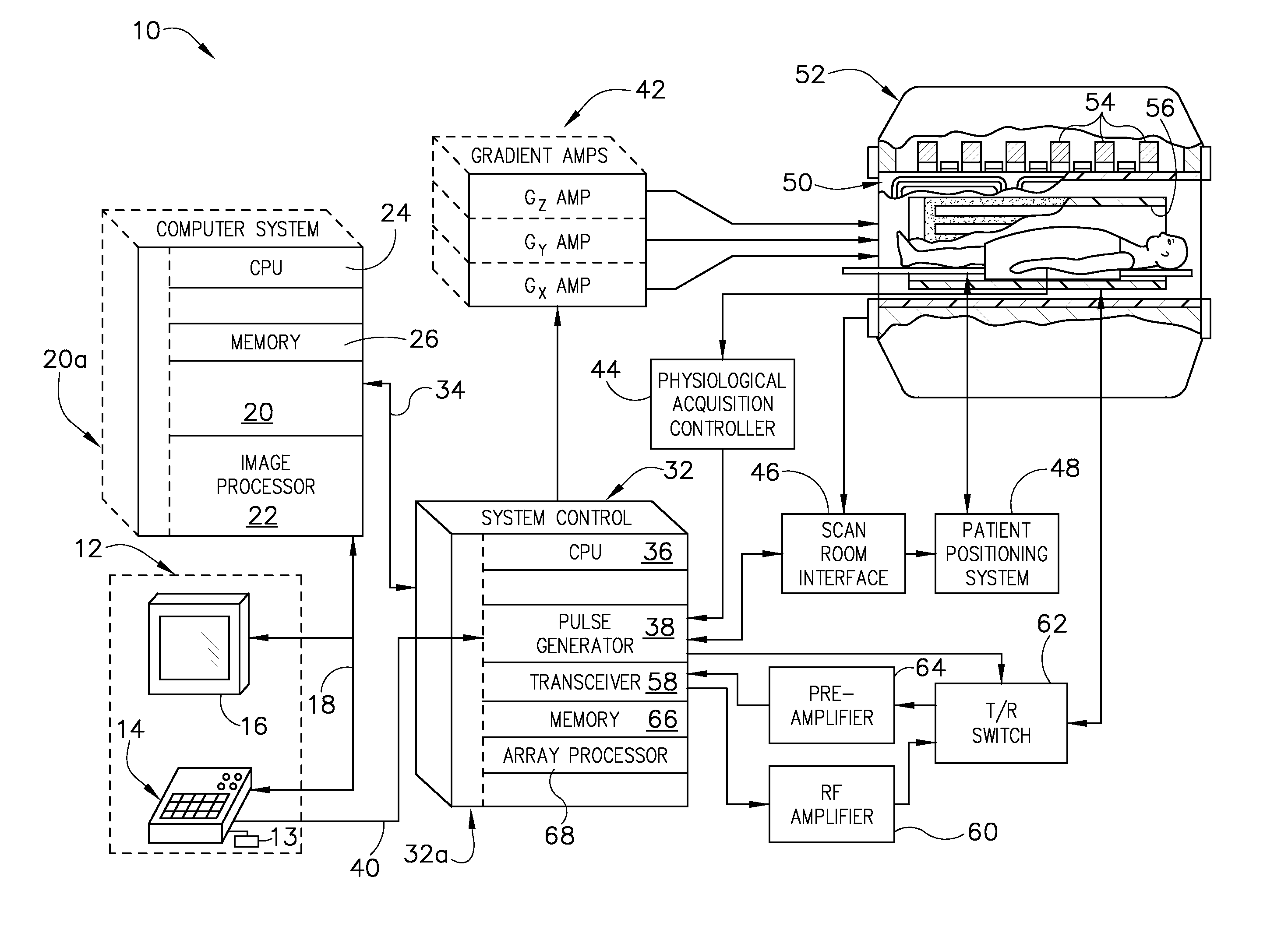
[0019]Referring to FIG. 1, the major components of a preferred magnetic resonance imaging (MRI) system 10 incorporating an embodiment of the invention are shown. The operation of the system is controlled from an operator console 12 which includes a keyboard or other input device 13, a control panel 14, and a display screen 16. The console 12 communicates through a link 18 with a separate computer system 20 that enables an operator to control the production and display of images on the display screen 16. The computer system 20 includes a number of modules which communicate with each other through a backplane 20a. These include an image processor module 22, a CPU module 24 and a memory module 26, which may include a frame buffer for storing image data arrays. The computer system 20 communicates with a separate system control 32 through a high speed serial link 34. The input device 13 can include a mouse, joystick, keyboard, track ball, touch activated screen, light wand, voice control...


PUM


Abstract

An apparatus includes a first RF coil integrated into a first printed circuit board (PCB) and a second RF coil integrated into the first PCB. The apparatus also includes a tuning member positioned adjacently to the first PCB and inductively coupled to the first and second RF coils, the tuning member configured to minimize a mutual inductance formed between the first and second RF coils via modification of a coupling constant between the first and second RF coils.

Description

BACKGROUND OF THE INVENTION[0001]Embodiments of the invention relate generally to MR coils and, more particularly, to an apparatus and method of decoupling MR coils.[0002]When a substance such as human tissue is subjected to a uniform magnetic field (polarizing field B0), the individual magnetic moments of the spins in the tissue attempt to align with this polarizing field, but precess about it in random order at their characteristic Larmor frequency. If the substance, or tissue, is subjected to a magnetic field (excitation field B1) which is in the x-y plane and which is near the Larmor frequency, the net aligned moment, or “longitudinal magnetization”, MZ, may be rotated, or “tipped”, into the x-y plane to produce a net transverse magnetic moment Mt. A signal is emitted by the excited spins after the excitation signal B1 is terminated and this signal may be received and processed to form an image.[0003]When utilizing these signals to produce images, magnetic field gradients (Gx, G...

Claims


Application Information

Patent Timeline
IPC IPC(8): G01R33/44
CPCG01R33/34007G01R33/365G01R33/3415
Inventor BOSKAMP, EDDY BENJAMIN
Owner GENERAL ELECTRIC CO
Why Eureka
Try Eureka