Guiding device

a guiding device and guiding technology, applied in the direction of optical light guides, electric lighting sources, lasers, etc., can solve the problems of high cost, long work time, increased cost, etc., and achieve the effects of low cost, simple construction and installation, and exceptional visibility

Inactive Publication Date: 2011-06-23
PANASONIC CORP
View PDF34 Cites 11 Cited by
  • Summary
  • Abstract
  • Description
  • Claims
  • Application Information

AI Technical Summary

Benefits of technology

[0010]It is an object of the present invention to provide a guiding device that excels in visibility, while being simple in construction and installation at a low cost.

Problems solved by technology

In particular, when long-distance irradiation is performed, cost is increased.
Another problem is that when the laser light source should be replaced, for example, at the end of service life thereof, large-scale road work is required, and the work takes a long time and requires a high cost.

Method used


Image

  • Guiding device
  • Guiding device
  • Guiding device

Examples


embodiment 1

[0035]An embodiment of the present invention will be described below with reference to FIG. 1 to FIG. 11.

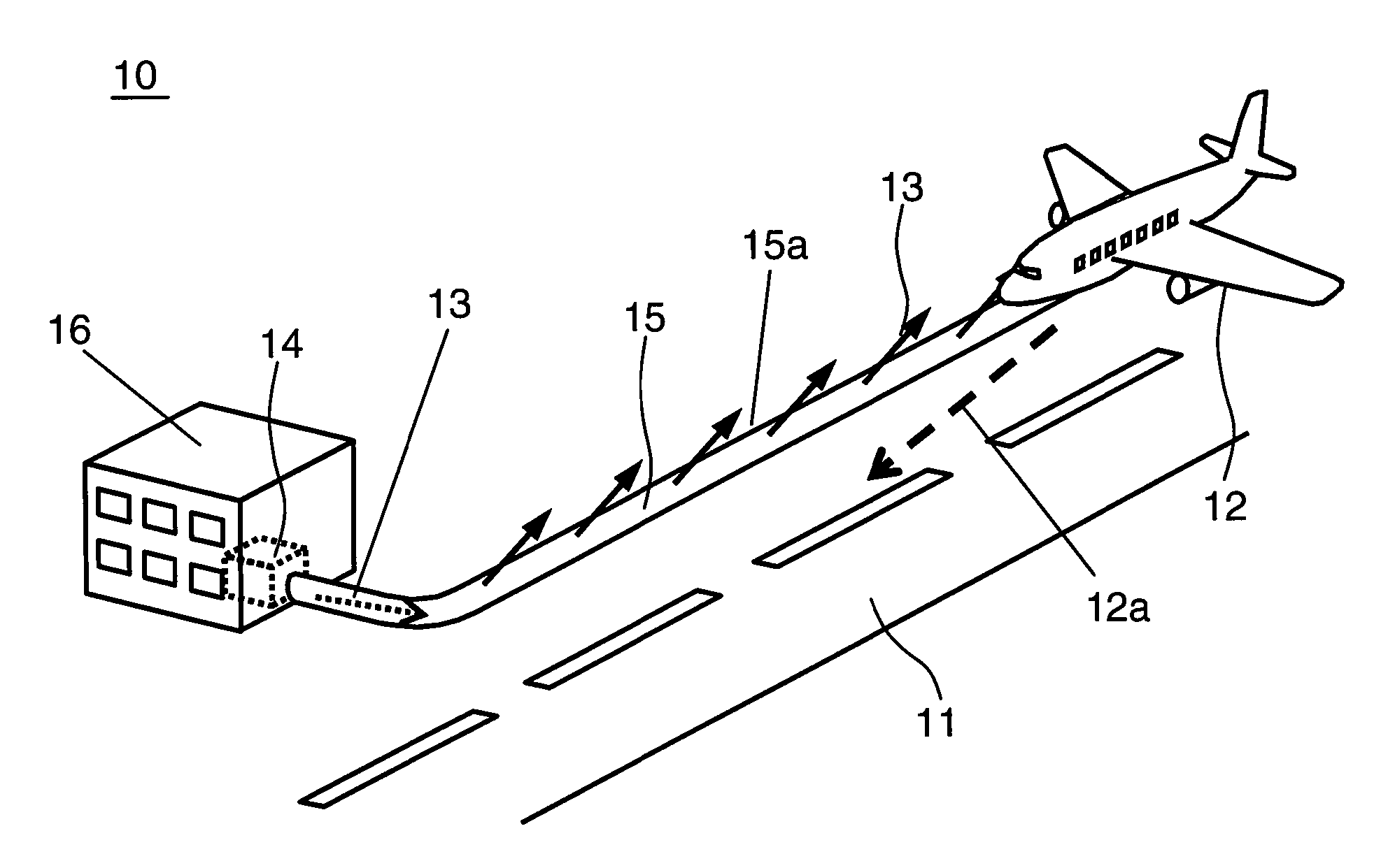
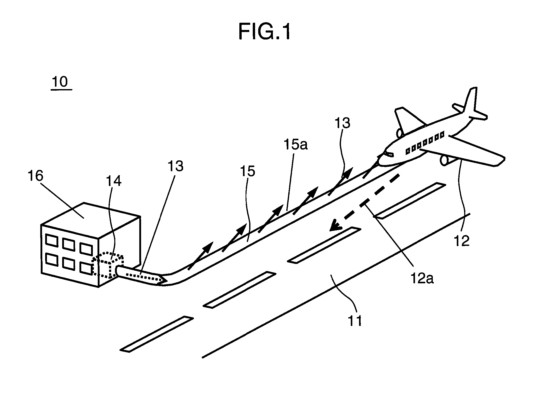
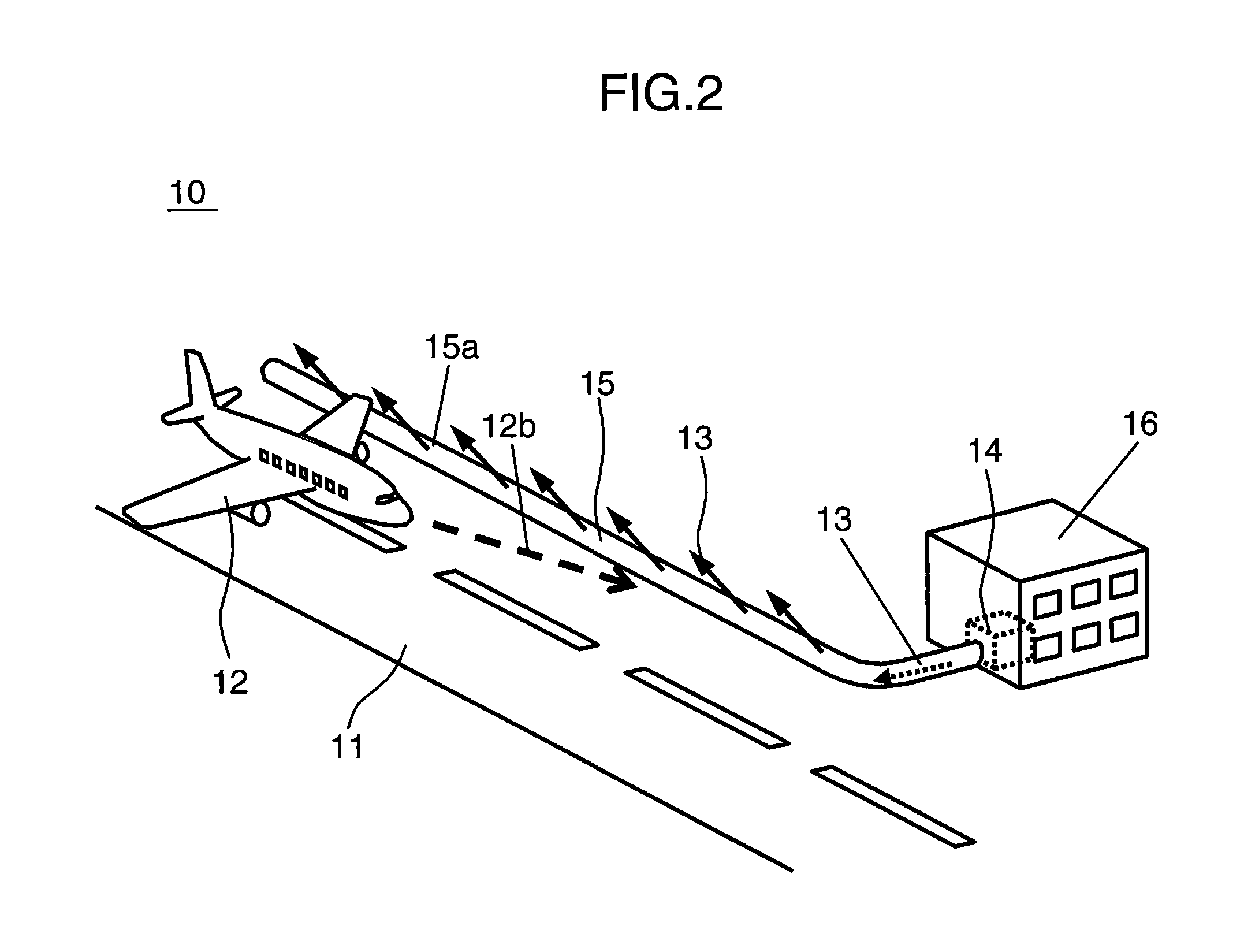
[0036]FIG. 1 and FIG. 2 illustrate a case in which a guiding device 1 is used as a guidance light of a runway of an airport in one configuration example of the guiding device of the present embodiment.

[0037]FIG. 1 shows a state in which an airplane 12 (mobile body) lands in the direction of an arrow 12a on a runway (road surface) 11 of an airport. FIG. 2 shows a state in which the airplane 12 (mobile body) takes off in the direction of an arrow 12b.

[0038]As shown in FIG. 1 and FIG. 2, the guiding device 10 of the present embodiment is provided with a laser light source 14 that emits a laser beam 13 and a linear guiding portion 15 composed of a fiber 15a that guides the laser beam 13 and is disposed on and along the runway 11 where the airplane 12 moves. The linear guiding portion 15 has a function of guiding the airplane 12 by irradiating the laser beam 13 with good directivity ...

embodiment 2

[0105]Another embodiment of the present invention will be described below with reference to FIG. 12 to FIG. 17.

[0106]FIG. 12 is a top view illustrating a schematic configuration of a guiding device of the present embodiment. FIG. 13 is a perspective view representing an example in which the linear guiding portion of the guiding device of the present embodiment is disposed along the surface road of a highway or a general road. FIG. 14 is a perspective view representing an example in which the linear guiding portion of the guiding device of the present embodiment is disposed along the curved surface road of a highway or a general road. FIG. 15 is a perspective view representing an example in which the linear guiding portion of the guiding device of the present embodiment is disposed along the surface road inside a tunnel.

[0107]A guiding device 100 shown in FIG. 12 is used as a guidance light of a road surface 101 when an automobile 102 is parked or the parked automobile 102 is driven ...

embodiment 3

[0138]A guiding device according to yet another embodiment of the present invention will be described below with reference to FIG. 18A and FIG. 18B.

[0139]FIG. 18A is a plan view illustrating a schematic configuration of a guiding device 140 of the present embodiment. FIG. 18B is a cross-sectional view taken along the 18B-18B line in FIG. 18A.

[0140]As shown in FIG. 18A, the guiding device 140 of the present embodiment includes a laser light source 14 that emits a laser beam 13 and a linear guiding portion 141 composed of fibers 142a and 142b that guide the laser beam 13 and are disposed along a road surface 101 where an automobile (mobile body) 102 travels.

[0141]In this configuration, as shown in FIG. 18A and FIG. 18B, the fibers 142a and 142b are disposed on a top portion 143a of a side surface of a convex central separation zone 143 disposed on the road surface 101.

[0142]The fibers 142a and 142b may have a configuration including a diffusing material 15d, for example, as in the fib...


PUM


Abstract

A guiding device includes: a laser light source that emits a laser beam; and a linear guiding portion that propagates the laser beam and is extended in the guiding direction on a road surface on which a mobile body moves. The linear guiding portion is provided with a function of radiating the laser beam in the guiding direction from the surface where linear guiding portion extends, while propagating the laser beam, and guiding the mobile body by light.

Description

TECHNICAL FIELD[0001]The present invention relates to a guiding device that adequately guides a mobile body such as a human, a vehicle, and an airplane.BACKGROUND ART[0002]Road display devices are needed that allow, for example, a driver to drive safely a vehicle such as an automobile in the nighttime or in dark locations, or to park the vehicle safely in a parking lot in a dark sites.[0003]A “Self-Emitting Road Rivet” that enables a vehicle driver to see clearly a horizontal light-emitting surface from a distance and also to enable an approaching vehicle driver or pedestrian to see clearly an upward light-emitting surface has been suggested as such a road display device (see, for example, Patent Document 1). Such a road display device is provided with an accommodation portion in an adequate installation side on a road, a light-emitting diode is disposed in the accommodation portion, the light emitted from the light-emitting diode is guided on the ground by fibers and the arrangemen...

Claims


Application Information

Patent Timeline
Patent Type & Authority Applications(United States)
IPC IPC(8): G08G1/095H01S3/00H05B37/02G08G5/06B64F1/36E01F9/576E01F9/582F21S2/00F21V8/00G02B6/00G09F13/00G09F19/22
CPCE01F9/002E01F9/085G08G1/096716G08G1/096758G09F19/22G08G5/0026G08G5/025G08G5/065G08G1/096775G05D1/0083E01F9/582E01F9/20
Inventor SHIKII, SHINICHIKODAWAKI, SHINICHIYAMAMOTO, KAZUHISAFURUYA, HIROYUKIITOH, TATSUO
Owner PANASONIC CORP
Why Eureka
Try Eureka