Methods and systems for detection of hazard to aviation due to convective weather

a technology of convective weather and detection methods, applied in the direction of navigation instruments, using reradiation, instruments, etc., can solve problems such as aviation turbulence that is hazardous, and achieve the effect of improving the degree of hazard assessment and improving the output of weather information

Active Publication Date: 2011-06-23
HONEYWELL INT INC
View PDF32 Cites 37 Cited by
  • Summary
  • Abstract
  • Description
  • Claims
  • Application Information

AI Technical Summary

Benefits of technology

[0002]An assessment of whether a convective weather cell is a hazard is more properly made by an evaluation of the amount of vertical development of the cell. The greater the vertical extent and amount of precipitation maintained aloft, the greater is the vertical air velocity, which then produces turbulence that is hazardous to aviation. Therefore, to improve the assessment of the degree of hazard resulting from convective weather, there is a need to include the amount of vertical development of convection.
[0003]The present invention provides systems and methods for improving output of weather information. A weather radar system receives weather reflectivity values. A processing device stores the received weather reflectivity values into a three-dimensional buffer, calculates a sum of the reflectivity value stored in a column of cells within the three-dimensional buffer, and assigns a first hazard indication to the cells of the column when the result of the calculation is above a first threshold. A display device generates a weather display based on data stored in the three-dimensional buffer. The weather display includes a display icon associated with the hazard indication when a cell from the three-dimensional buffer has been selected for the weather display.

Problems solved by technology

The greater the vertical extent and amount of precipitation maintained aloft, the greater is the vertical air velocity, which then produces turbulence that is hazardous to aviation.

Method used


Image

  • Methods and systems for detection of hazard to aviation due to convective weather
  • Methods and systems for detection of hazard to aviation due to convective weather
  • Methods and systems for detection of hazard to aviation due to convective weather

Examples


Embodiment Construction

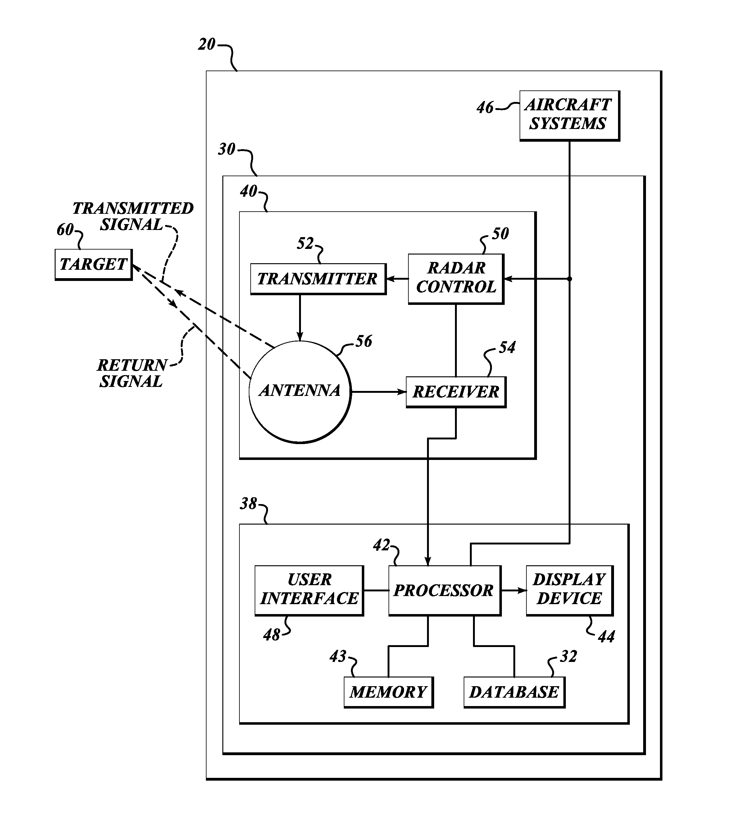
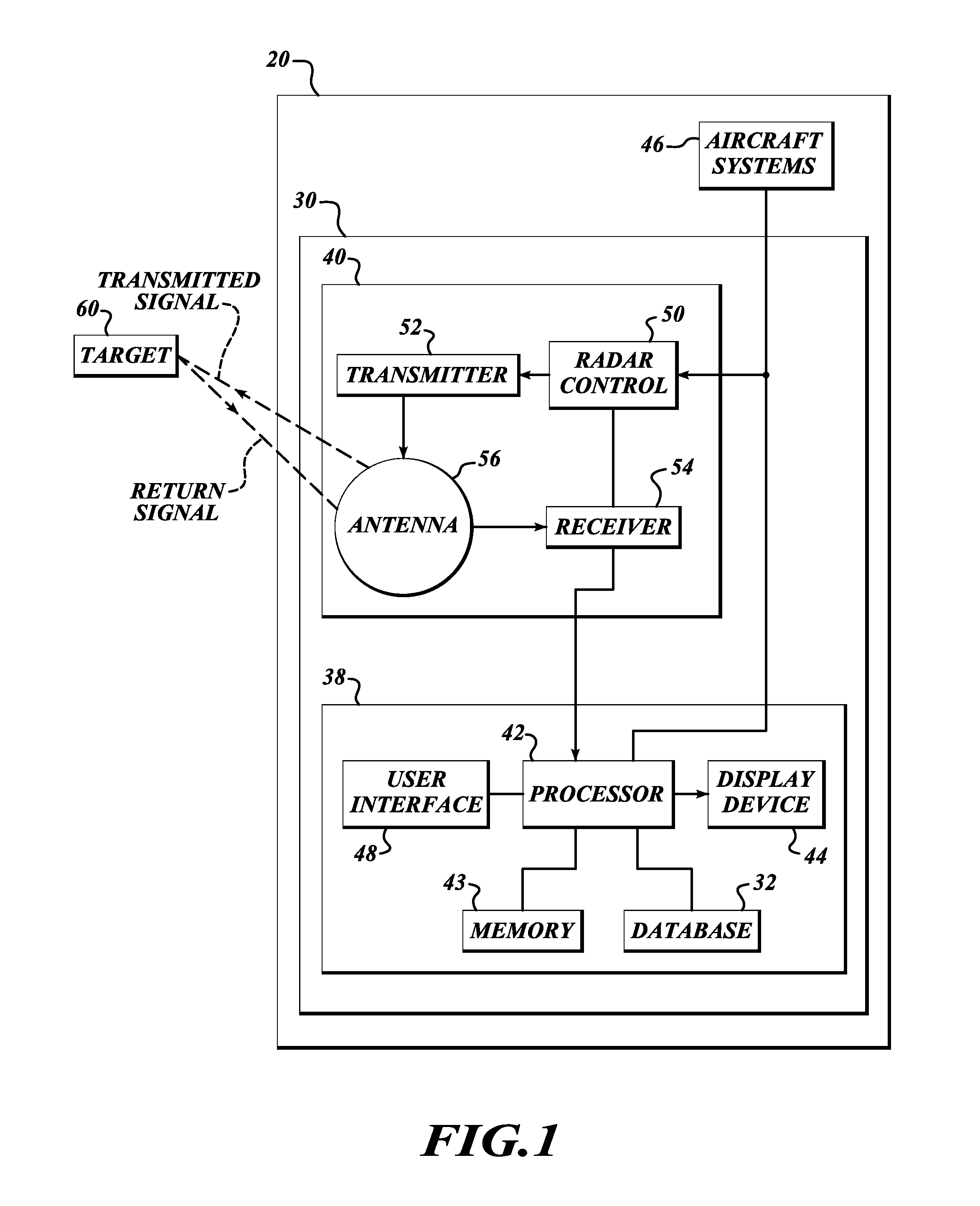
[0008]FIG. 1 illustrates an aircraft 20 that includes a weather display system 30 for providing an improved radar return. The exemplary weather display system 30 includes a weather radar system 40 and a display / interface front-end 38, and receives information from other aircraft systems 46. The display / interface front-end 38 includes a processor 42, memory 43, a display device 44, a user interface 48, and a database 32. An example of the radar system 40 includes a radar controller 50 (configured to receive control instructions from the user interface 48), a transmitter 52, a receiver 54, and an antenna 56. The radar controller 50 controls the transmitter 52 and the receiver 54 for performing the sending and receiving of signals through the antenna 56. The weather radar system 40 and the display / interface front-end 38 are electronically coupled to the aircraft systems 46.

[0009]Radar relies on a transmission of a pulse of electromagnetic energy, referred to herein as a signal. The ant...


PUM


Abstract

Systems and methods for improving output of weather information. A weather radar system receives weather reflectivity values. A processing device stores the received weather reflectivity values into a three-dimensional buffer, calculates a sum of the reflectivity value stored in a column of cells within the three-dimensional buffer, and assigns a first hazard indication to the cells of the column when the result of the calculation is above a first threshold. A display device generates a weather display based on data stored in the three-dimensional buffer. The weather display includes a display icon associated with the hazard indication when a cell from the three-dimensional buffer has been selected for the weather display.

Description

BACKGROUND OF THE INVENTION[0001]Airborne weather radars are used to identify convective weather that generates turbulence that can be hazardous to aviation. The detection is typically based only on radar reflectivity of the weather that exists at a selected part of a storm. The degree of hazard is assumed to be related to this reflectivity. However, this is not always a valid assumption to make.SUMMARY OF THE INVENTION[0002]An assessment of whether a convective weather cell is a hazard is more properly made by an evaluation of the amount of vertical development of the cell. The greater the vertical extent and amount of precipitation maintained aloft, the greater is the vertical air velocity, which then produces turbulence that is hazardous to aviation. Therefore, to improve the assessment of the degree of hazard resulting from convective weather, there is a need to include the amount of vertical development of convection.[0003]The present invention provides systems and methods for ...

Claims


Application Information

Patent Timeline
Patent Type & Authority Applications(United States)
IPC IPC(8): G01S13/95
CPCG01S7/04G01S13/953G01W1/08G01W1/06G01W1/00Y02A90/10
Inventor CHRISTIANSON, PAUL
Owner HONEYWELL INT INC
Why Eureka
Try Eureka