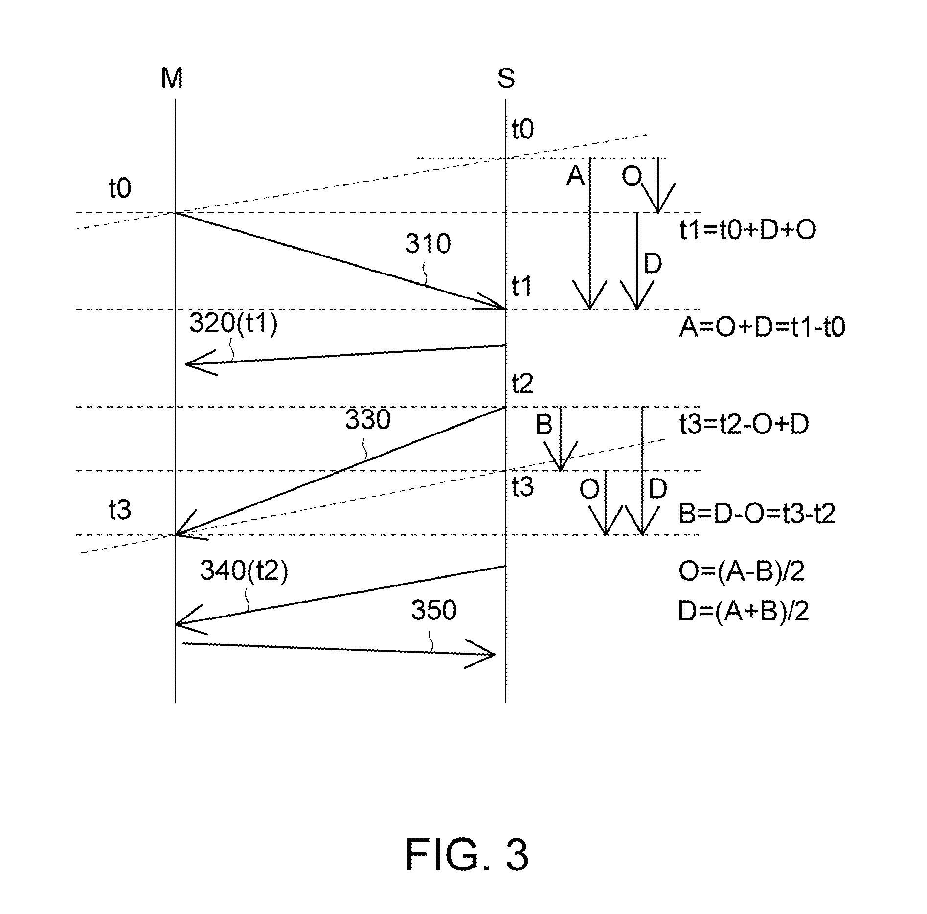
[0008]According to a first exemplary embodiment of the disclosure, a precision time synchronization method for a network having a local master node and at least one slave node is provided. The method includes the steps of: outputting a synchronization packet from the local master node to the slave node, and recording, by the local master node, a first time of outputting the synchronization packet; recording, by the slave node, a second time of receiving the synchronization packet when the slave node receives the synchronization packet; adding, by the slave node, the second time to a sync response packet after receiving the synchronization packet, and returning, by the slave node, the sync response packet to the local master node; extracting, by the local master node, the second time from the sync response packet after the local master node receives the sync response packet, so that the local master node establishes a first time difference equation expressing that a difference between the second time and the first time is equal to a time offset plus a packet transmission delay time; sending, by the slave node, a slave sync packet to the local master node, and recording, by the slave node, a third time of outputting the slave sync packet; recording, by the local master node, a fourth time of receiving the slave sync packet after the local master node receives the slave sync packet; sending, by the slave node, a slave node notification packet to the local master node, and adding, by the slave node, the third time to the slave node notification packet; establishing, by the local master node, a second time difference equation expressing that a difference between the fourth time and the third time is equal to the packet transmission delay time minus the time offset, wherein the local master node calculates the time offset between the local master node and the slave node and the packet transmission delay time according to the first and second time difference equations; and outputting, by the local master node, a clock update packet to the slave node, wherein the clock update packet carries the time offset between the local master node and the slave node and the packet transmission delay time, so that the slave node is time synchronized with the local master node after the slave node performs time calibration according to the time offset.
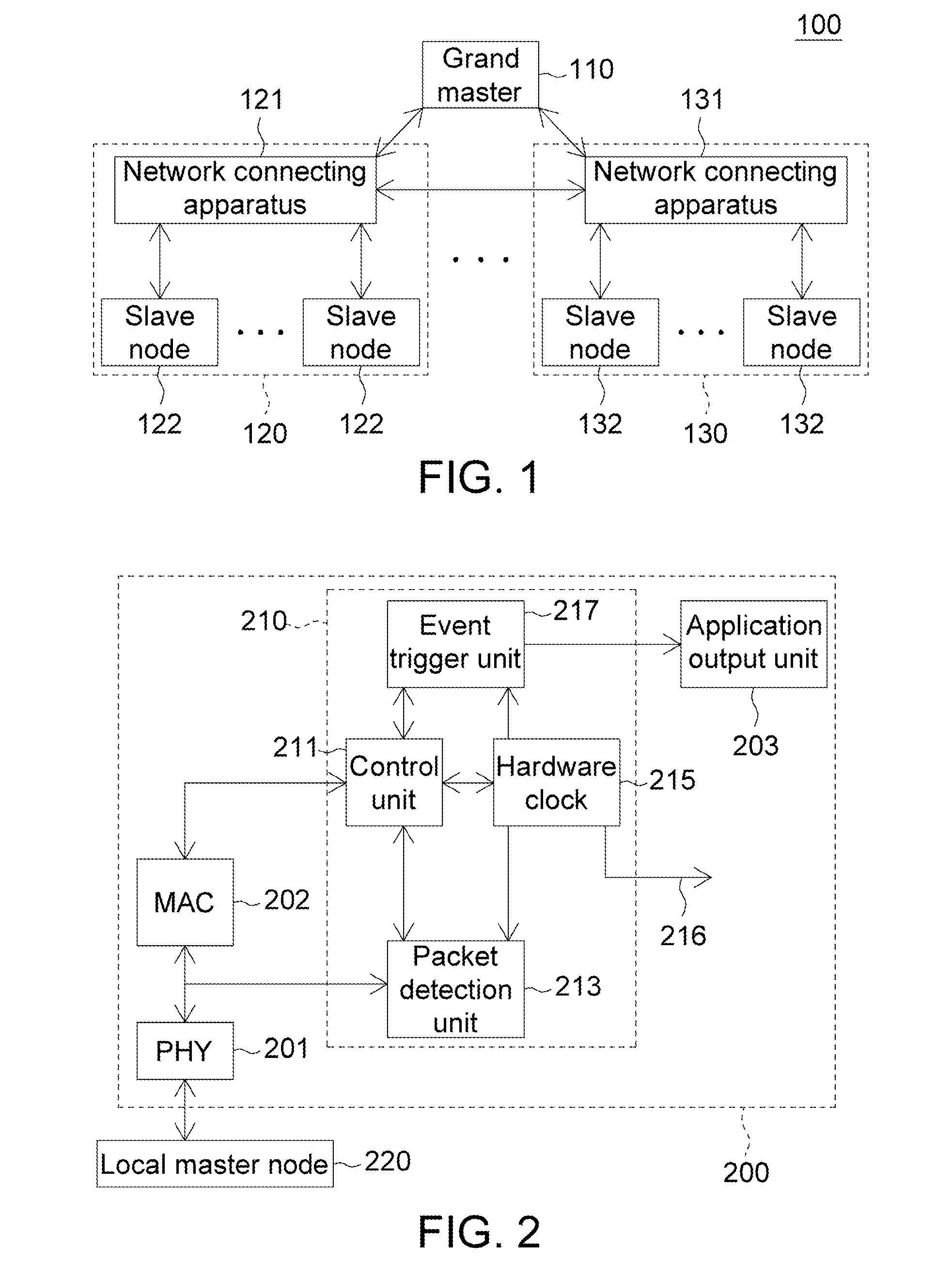
[0009]According to a second exemplary embodiment of the disclosure, a slave node coupled to a local master node in a network is provided. The slave node includes a packet detection unit, a hardware clock and a control unit. The packet detection unit detects whether the slave node receives or sends a synchronization protocol packet and records a synchronization protocol packet receiving time and a synchronization protocol packet sending time The control unit is coupled to and controls the packet detection unit and the hardware clock. The control unit reads out the synchronization protocol packet receiving time and the synchronization protocol packet sending time from the packet detection unit, and informs the local master node about the synchronization protocol packet receiving time and the synchronization protocol packet sending time. The control unit receives (1) a time offset between the local master node and the slave node and (2) a packet transmission delay time which are both calculated by the local master node. The control unit adjusts the hardware clock according to the time offset and the packet transmission delay time, so that the slave node and the local master node are time synchronized.
[0010]According to a third exemplary embodiment of the disclosure, a precision time synchronization method applied to a slave node connected to a local master node is provided. The method includes the steps of: receiving, by the slave node, a synchronization packet outputted from the local master node at a first time, and recording, by the slave node, a second time of receiving the synchronization packet; returning, by the slave node, a sync response packet containing the second time to the local master node after receiving the synchronization packet, wherein the local master node establishes a first time difference equation expressing that a difference between the second time and the first time is equal to a time offset plus a packet transmission delay time; sending, by the slave node, a slave sync packet to the local master node, and recording, by the slave node, a third time of outputting the slave sync packet, wherein the local master node receives the slave sync packet at a fourth time; sending, by the slave node, a slave node notification packet containing the third time to the local master node, such that the local master node establishes a second time difference equation expressing that a difference between the fourth time and the third time is equal to the packet transmission delay time minus the time offset, the local master node calculates both the time offset between the local master node and the slave node and the packet transmission delay time according to the first and second time difference equations; and receiving, by the slave node, a clock update packet outputted from the local master node, the clock update packet carrying the time offset between the local master node and the slave node and the packet transmission delay time, so that the slave node is time synchronized with the local master node after the slave node performs a time calibration according to the time offset.

