Eureka AIR delivers breakthrough ideas for toughest innovation challenges, trusted by R&D personnel around the world.

Method for making a desired pattern of a metallic nanostructure of a metal

a metal nanostructure and desired pattern technology, applied in the direction of liquid/solution decomposition chemical coating, transportation and packaging, coatings, etc., can solve the problem of affecting the removal effect of metal, and achieve the effect of simple and convenien

Inactive Publication Date: 2011-06-23
NAT TAIPEI UNIV OF TECH
View PDF2 Cites 13 Cited by
  • Summary
  • Abstract
  • Description
  • Claims
  • Application Information

AI Technical Summary

Benefits of technology

[0010]Therefore, an object of the present invention is to provide a simple and convenient method for making a desired pattern of a metallic nanostructure of a metal that can overcome the aforesaid drawback associated with the prior art.

Problems solved by technology

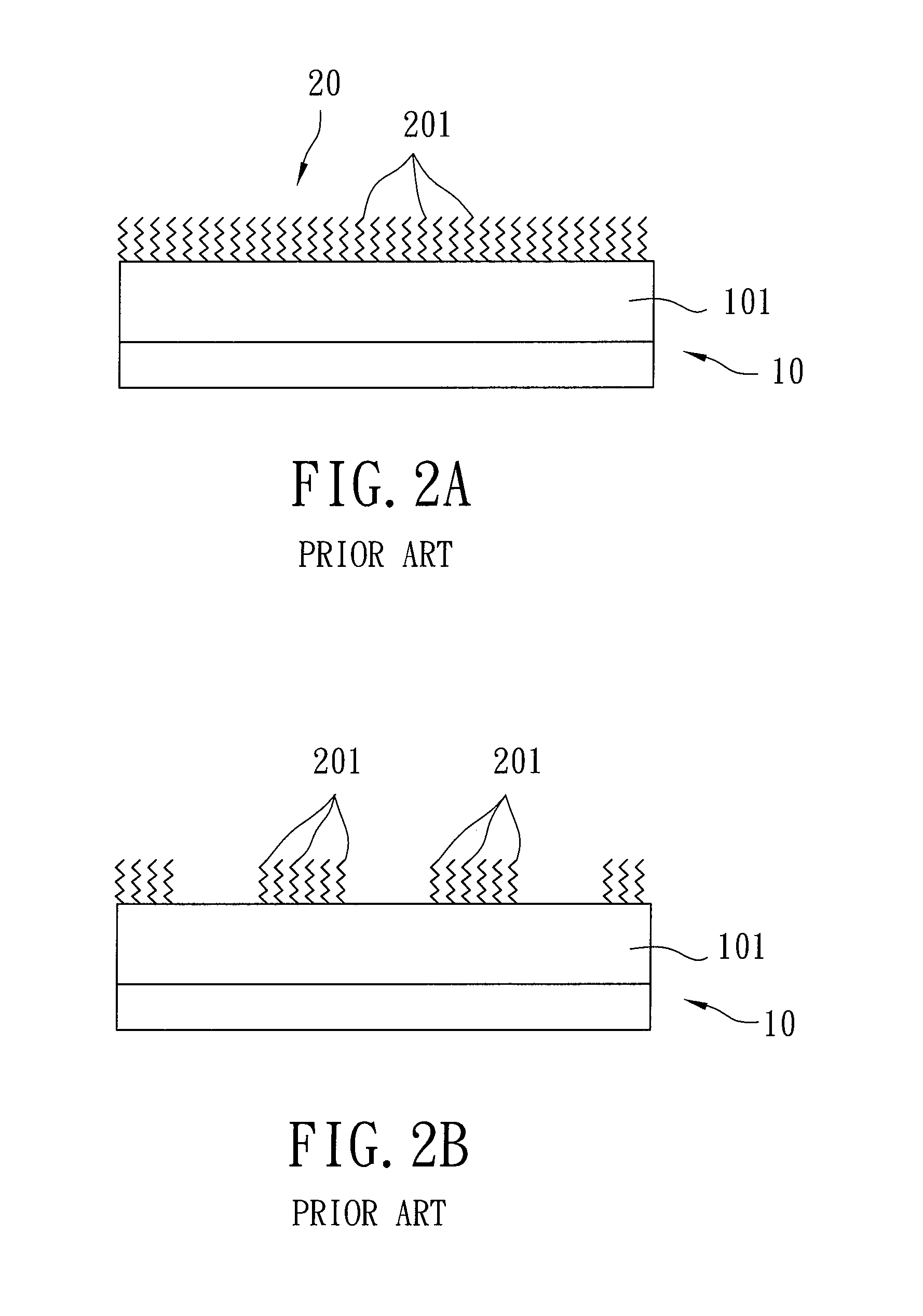
In the second and third conventional methods, since the nanoscopic tip is used to remove a portion of the self-assembled monolayer or the resist layer on the substrate, there is a tendency to damage the substrate during the removal operation.

Method used


Image

  • Method for making a desired pattern of a metallic nanostructure of a metal
  • Method for making a desired pattern of a metallic nanostructure of a metal
  • Method for making a desired pattern of a metallic nanostructure of a metal

Examples


Embodiment Construction

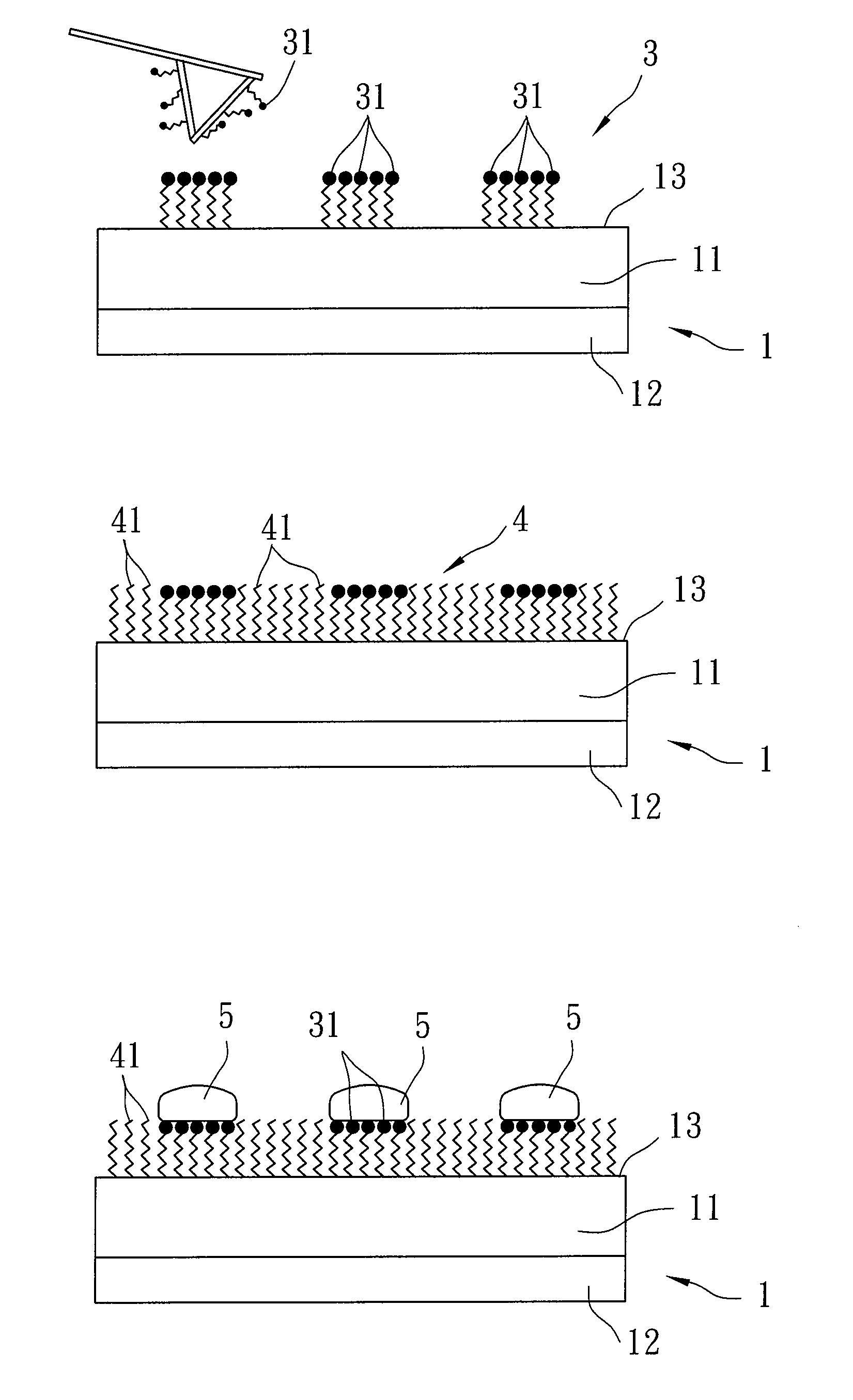
[0017]Referring to FIGS. 4A, 4B, and 4C, a preferred embodiment of a method for making a desired pattern of a metallic nanostructure of a metal according to this invention includes: (a) forming the desired pattern of a self-assembled monolayer matrix 3 of a first organic compound 31 on a pattern-forming surface 13 of a substrate 1 through nanolithography, the first organic compound 31 having a head group bonded to the substrate 1 and a tail group distal from the substrate 1 and selected to be active toward deposition of the metal on the self-assembled monolayer matrix 3, as best shown in FIG. 4A; (b) forming an inert layer 4 of a second organic compound 41 on a portion of the pattern-forming surface 13 of the substrate 1 that is exposed from the self-assembled monolayer matrix 3 by contacting an assembly of the substrate 1 and the self-assembled monolayer matrix 3 with a solution containing the second organic compound 41, the second organic compound 41 having a head group bonded to ...


PUM

PropertyMeasurementUnit
Metallic bondaaaaaaaaaa
Affinityaaaaaaaaaa

Abstract

A method for making a desired pattern of a metallic nanostructure of a metal includes: (a) forming the desired pattern of a self-assembled monolayer matrix of a first organic compound on a substrate, the first organic compound having a tail group selected to be active toward deposition of the metal on the self-assembled monolayer matrix; (b) forming an inert layer of a second organic compound on the substrate by contacting an assembly of the substrate and the self-assembled monolayer matrix with a solution containing the second organic compound, the second organic compound having a tail group selected to be inactive toward the deposition of the metal on the inert layer; and (c) depositing the metal on the self-assembled monolayer matrix by contacting an assembly of the substrate, the self-assembled monolayer matrix and the inert layer with a solution containing metal ions, followed by reducing the metal ions.

Description

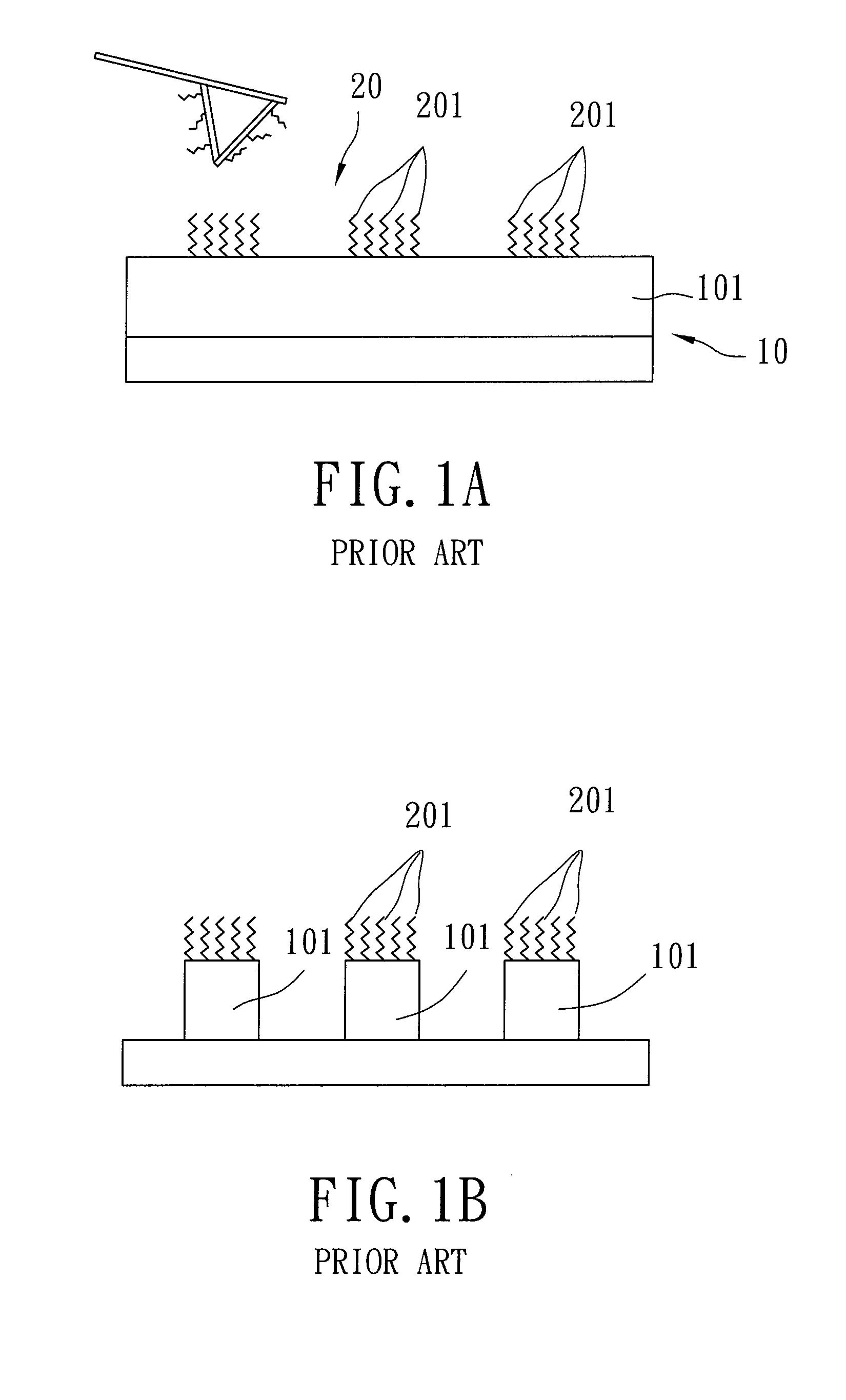
CROSS-REFERENCE TO RELATED APPLICATION[0001]This application claims priority of Taiwanese Application No. 098144459, filed on Dec. 23, 2009.BACKGROUND OF THE INVENTION[0002]1. Field of the Invention[0003]This invention relates to a method for making a desired pattern of a metallic nanostructure of a metal, more particularly to a method for making a desired pattern of a metallic nanostructure of a metal using nanolithography.[0004]2. Description of the Related Art[0005]Lithography is an important technique in microfabrication, nanofabrication, and preparation of molecular electronics. Dip pen nanolithography (DPN) is widely used for making molecular electronics.[0006]Referring to FIGS. 1A and 1B, a first conventional method involving the use of the DPN technique for making a desired pattern of a metallic nanostructure is shown to include forming a patterned layer 20 of an organic compound 201 on a metal layer 101 of a substrate 10 through the use of a nanoscopic tip coated with the o...

Claims


Application Information

Patent Timeline
IPC IPC(8): B32B3/10B05D1/36B32B15/00
CPCB82Y40/00C23C18/1608C23C18/1658Y10T428/24917H05K3/182H05K2203/122C23C18/1844
Inventor CHANG, YU-HSUWANG, JIA-SIN
Owner NAT TAIPEI UNIV OF TECH
Why Eureka
Eureka Blog
Learn More