Control of a voltage source converter using synchronous machine emulation

a voltage source converter and synchronous machine technology, applied in the direction of dc-ac conversion without reversal, process and machine control, instruments, etc., can solve the problems of system inability to use, inverter not contributing to the voltage control of the grid, etc., to reduce the grid voltage magnitude and maintain the stability of the grid

Inactive Publication Date: 2011-06-23
ABB TECH AG +1
View PDF9 Cites 20 Cited by
  • Summary
  • Abstract
  • Description
  • Claims
  • Application Information

AI Technical Summary

Benefits of technology

[0024]The present invention has a number of advantages. The control contributes to the control of the grid. A reduction of the grid voltage magnitude can be counteracted by an injection of reactive power from the voltage source converter. It furthermore provides stability regardless of the grid characteristics. This is important since it is often necessary to maintain stability of the grid regardless of the grid strength and regardless of the dynamics of the load, machines and other converters connected to the grid. The inventive concept can also be applied for passive grids. Voltage source converter control using an emulation of the electrical dynamics of a non-salient synchronous machine is furthermore promising regarding use in relation to weak or passive grids, including wind-farm applications. Tuning of a control device may then become much more straight-forward and robust as compared with conventional control devices, since it may be possible to consider experience in dynamics and control of synchronous machines.

Problems solved by technology

In addition the system cannot be used in situations when the voltage source converter is to control the frequency of the grid.
However, the inverter does not contribute to the voltage control of the grid.

Method used


Image

  • Control of a voltage source converter using synchronous machine emulation
  • Control of a voltage source converter using synchronous machine emulation
  • Control of a voltage source converter using synchronous machine emulation

Examples


Embodiment Construction

[0033]In the following, a detailed description of preferred embodiments of a device and a method according to the present invention will be given.

[0034]The present invention may be provided in a system, which is to be connected to a power or utility grid via voltage source converters (VSCs). Such systems include systems for generation and transmission of electrical DC or AC power, i.e. high-voltage or ultra high-voltage power transmission and generation systems.

[0035]When a voltage source converter is connected to a utility or power grid, it may be desirable to let the converter contribute to the control of the grid. The present invention is directed towards enabling such contributions to be made by a voltage source converter.

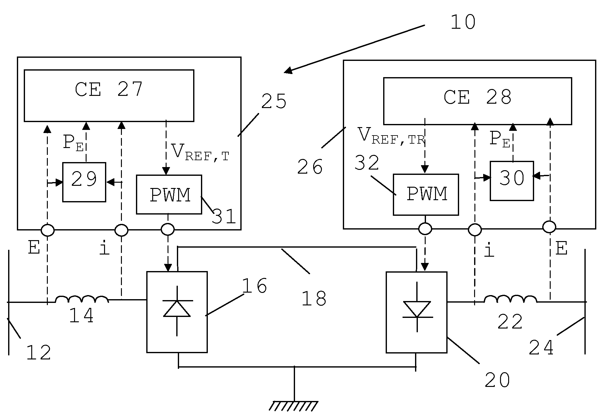
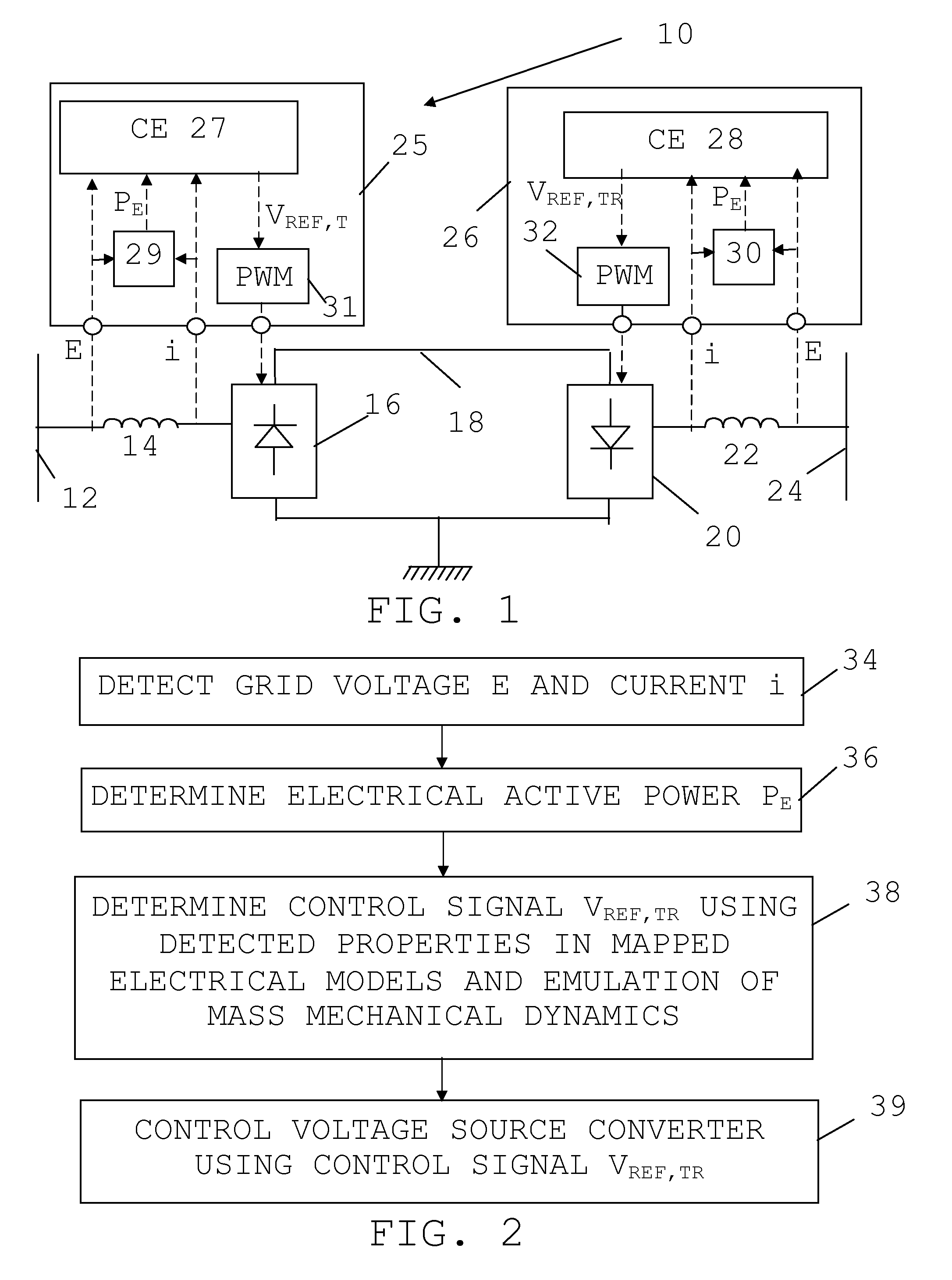
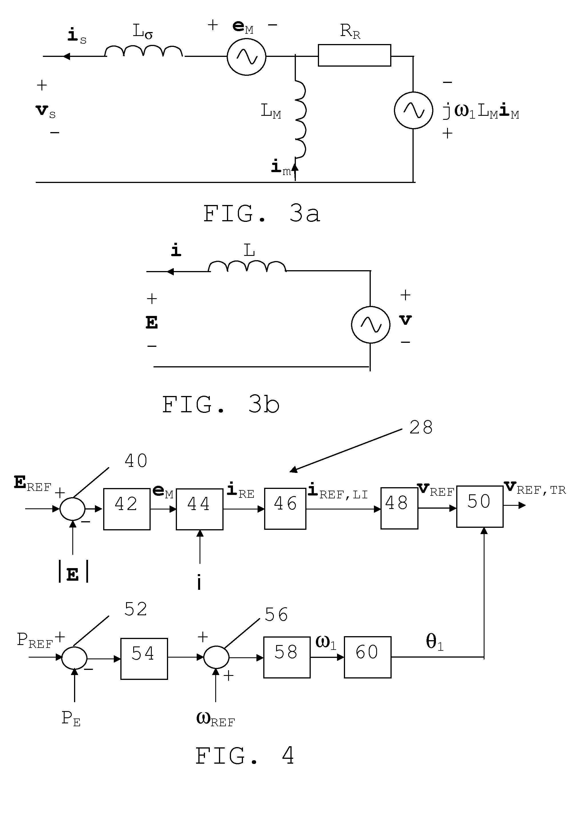
[0036]In FIG. 1 there is schematically shown a single line diagram of an exemplifying power transmission system in the form of a High Voltage Direct Current (HVDC) system, i.e. a high-voltage (above 50 kV) or ultra high-voltage (above 400 kV) power transmission...


PUM


Abstract

The invention concerns a method, device and computer program product for controlling a voltage source converter (16; 20) connected to a power grid (12; 24). The device (25; 26) includes a first input for receiving at least one detected electrical property (E, i) of an interface between the grid and the voltage source converter, and a control entity (27; 28) arranged to control the voltage source converter (16; 20) through using a control signal (vREF,TR) obtained through using a mapping of an electrical model of a non-salient synchronous machine onto an electrical model of the voltage source converter and through applying the detected electrical property of the interface between the grid and the voltage source converter in said mapped model, where the electrical model of the non-salient synchronous machine reflects the electrical dynamics of this synchronous machine.

Description

FIELD OF INVENTION[0001]The present invention generally relates to voltage source converters. The present invention is more particularly directed towards a method, device and computer program product for controlling a voltage source converter connected to a power grid.BACKGROUND[0002]The number of voltage source converters (VSCs) that are connected to the average utility grid is steadily increasing. Applications include high-voltage direct current (HVDC) transmissions, static synchronous compensators (STATCOMs), back-to-back motor drives, distributed generation and wind-turbine generators.[0003]In some cases, particularly when the rated power capacity is high, i.e. in the MVA range, it may be desirable for the voltage source converter to contribute to the voltage control of the grid. The voltage source converter should thus control the grid-voltage magnitude at the bus to which it is connected. This is particularly true for VSC-HVDC terminals and the fundamental purpose of a STATCOM...

Claims


Application Information

Patent Timeline
Patent Type & Authority Applications(United States)
IPC IPC(8): G06F1/26
CPCH02J3/34Y02E60/60H02M7/797H02J3/36H02P9/02H02J3/38H02J3/16H02M7/48
Inventor HARNEFORS, LENNART
Owner ABB TECH AG
Why Eureka
Try Eureka