
Micromechanical component and method for operating a micromechanical component

a micromechanical and component technology, applied in the direction of speed/acceleration/shock measurement, measurement devices, instruments, etc., can solve the problem of no provision for sensing, and achieve the effects of less power consumption, less manufacturing costs, and compactness

Active Publication Date: 2011-06-30
ROBERT BOSCH GMBH
View PDF2 Cites 29 Cited by
  • Summary
  • Abstract
  • Description
  • Claims
  • Application Information

AI Technical Summary

Benefits of technology

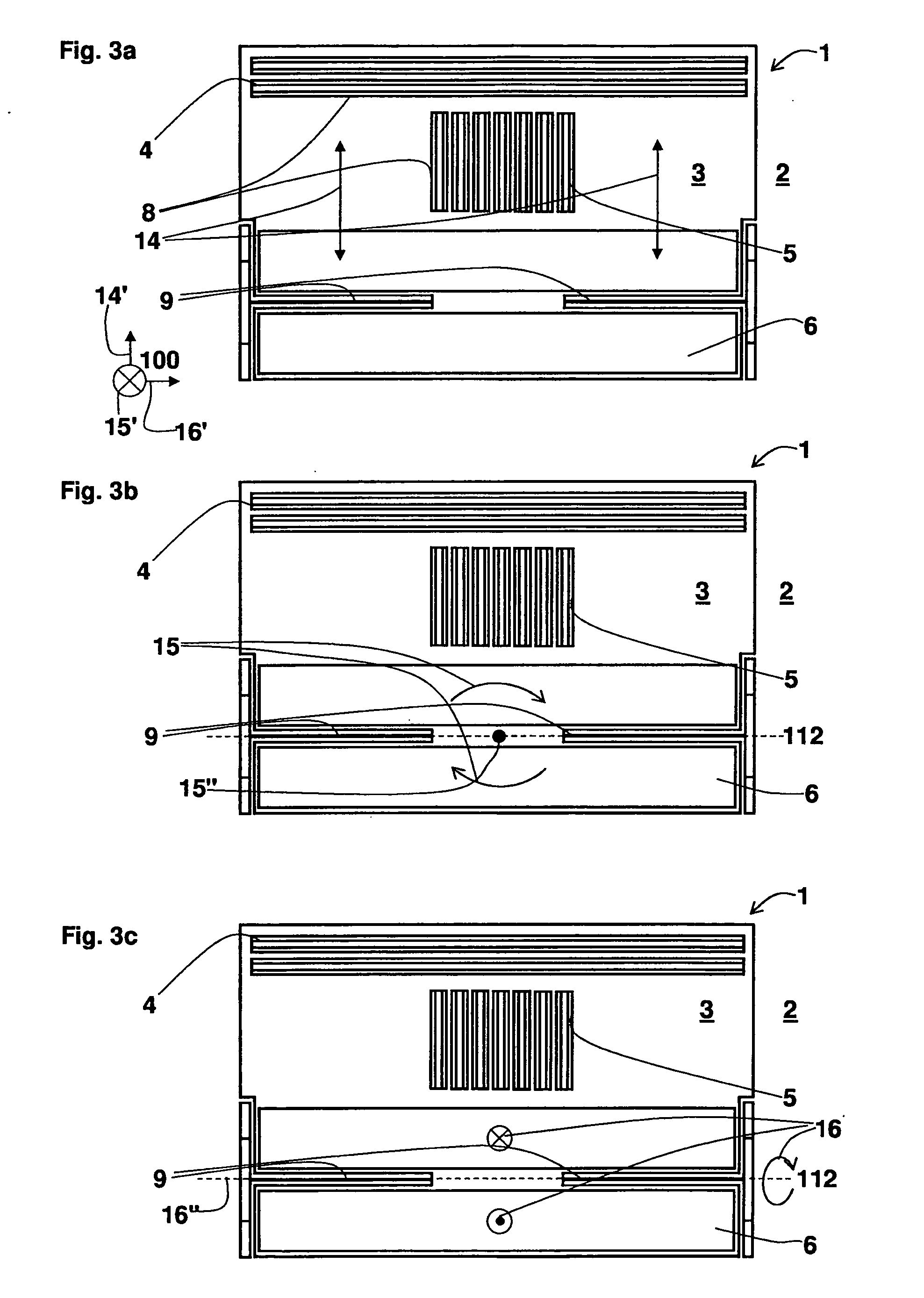
[0008]According to a preferred refinement, provision is made that the seismic mass is embodied as a rocker that is bearing-mounted in rotationally movable fashion in particular about the first and / or the second rotation axis. Advantageously, realization of the seismic mass as a rocker that is rotationally movable about the first and / or the second axis makes possible particularly simple implementation of the corresponding detection means, for example below the seismic mass, the rocker preferably having an asymmetrical mass distribution with reference to the respective rotation axis.
[0009]According to a further preferred refinement, provision is made that the first, second, and / or third detection means encompass electrodes, in particular for capacitive measurement of the first, second, and / or third deflection, the first and / or second detection means preferably being embodied as finger electrodes, and / or the third detection means preferably as planar electrodes. Particularly advantageously, the first, second, and / or third detection means, which preferably allow a comparatively precise detection or measurement of acceleration effects parallel to the first, the second, and / or the third direction by way of capacitive measurement of the first, second, and third deflection, can thus be realized in comparatively simple and economical fashion. The use of finger electrodes enables, particularly preferably, a differential measurement of the acceleration effects parallel to the first, the second, and / or the third direction.
[0011]According to a further preferred refinement, provision is made that the third detection means are disposed perpendicular to the main extension plane, overlapping the seismic mass. The third deflection is thus, particularly advantageously, measurable parallel to the third direction, which is preferably oriented perpendicular to the main extension plane. The asymmetrical mass distribution of the seismic mass with reference to the second rotation axis makes possible, particularly preferably, a differential evaluation of the third deflection by way of third detection means disposed “below” the seismic mass, thus rendering unnecessary the placement (comparatively complex in terms of process engineering) of electrodes “above” the seismic mass for differential measurement of the third deflection.

Problems solved by technology

Disadvantageously, however, no provision is made for sensing, with a single acceleration sensor, acceleration actions parallel to a plurality of directions that are perpendicular to one another.

Method used


Image

  • Micromechanical component and method for operating a micromechanical component
  • Micromechanical component and method for operating a micromechanical component
  • Micromechanical component and method for operating a micromechanical component

Examples


Embodiment Construction

[0021]In the various Figures, identical parts are always provided with the same reference characters and are therefore, as a rule, also each mentioned or named only once.

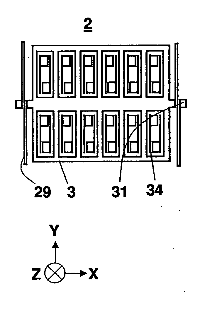
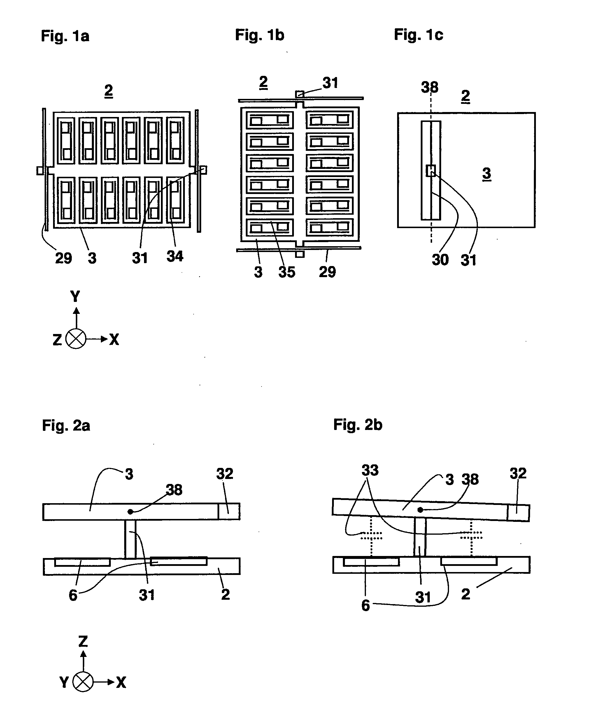
[0022]FIGS. 1a, 1b, and 1c are schematic views of acceleration sensors in accordance with the existing art that are sensitive in the X, Y, and Z directions; the acceleration sensor illustrated in FIG. 1a and sensitive parallel to the X direction has a substrate 2 and a seismic mass 3, the X direction extending parallel to a main extension plane of substrate 2 and seismic mass 3 being attached to substrate 2, by way of two spring elements 29 and two attachment anchors 31, in such a way that seismic mass 2 is movable parallel to the X direction relative to substrate 2. An acceleration force acting on the acceleration sensor and having a component parallel to the X direction generates, as a result of the inertia of seismic mass 3 with respect to substrate 2, a deflection of said mass parallel to the X direction. This d...


PUM


Abstract

A micromechanical component comprising a substrate, a seismic mass, and first and second detection means, the substrate having a main extension plane and the first detection means being provided for detection of a substantially translational first deflection of the seismic mass along a first direction substantially parallel to the main extension plane, and the second detection means further being provided for detection of a substantially rotational second deflection of the seismic mass about a first rotation axis parallel to a second direction substantially perpendicular to the main extension plane. The seismic mass can be embodied as an asymmetrical rocker, with the result that accelerations can be sensed as rotations. Detection can be accomplished via capacitive sensors.

Description

BACKGROUND OF THE INVENTION[0001]1. Field of the Invention[0002]The present invention proceeds from a micromechanical component.[0003]2. Description of Related Art[0004]Micromechanical components of this kind are generally known. The published German patent application document DE 197 19 779 A1, for example, discloses an acceleration sensor having an oscillating structure suspended movably on a substrate and deflectable in one direction on the basis of an acceleration action, and evaluation means for sensing an acceleration-related deflection of the oscillating structure. Disadvantageously, however, no provision is made for sensing, with a single acceleration sensor, acceleration actions parallel to a plurality of directions that are perpendicular to one another. Multi-channel acceleration measurement therefore requires the use of a plurality of such acceleration sensors that are oriented differently from one another.SUMMARY OF THE INVENTION[0005]The micromechanical component accord...

Claims


Application Information

Patent Timeline
Patent Type & Authority Applications(United States)
IPC IPC(8): G01P15/125G01P15/18
CPCG01P15/125G01P2015/0817G01P15/18G01P2015/0831
Inventor CLASSEN, JOHANNESTEBJE, LARS
Owner ROBERT BOSCH GMBH
Learn More