Loom for producing a woven article with a profiled cross section, in particular a rope

a technology of profiled cross section and weaving machine, which is applied in the direction of looms, auxiliary devices, textiles and papermaking, etc., can solve the problems of only allowing ropes of limited length, the cross section cannot be changed, and the machine has limited capacity, so as to prevent the deformation of the profile fabric, reduce the stress in the profile fabric produced, and improve the effect of reducing the tension in the profile fabri

Inactive Publication Date: 2011-06-30
TEXTILMA AG
View PDF20 Cites 10 Cited by
  • Summary
  • Abstract
  • Description
  • Claims
  • Application Information

AI Technical Summary

Benefits of technology

[0009]The cloth holder advantageously has an introduction slot, formed over the length of the shaping opening thereof, for introducing the warp threads. The introduction slot is designed here such that the introduced warp threads are prevented from sliding out. For this purpose, the introduction slot preferably has a wavy form. It is also advantageous for the cloth holder to have a split form in the direction of its shaping opening, so that, by removing a part of the cloth holder, the shaping opening is accessible in order to insert the warp threads.
[0010]It is advantageous that a heddle which is prestressed transversely to the warp thread course is present in the warp thread supply device upstream of the shedding device for each warp thread, in order to equalize alternating tensile stresses or differences of length between adjacent warp threads during weaving. At least one warp thread supply can be designed for a warp thread of relatively large diameter serving as a filler and can have a corresponding tension. Expediently, each heddle or the tensioning roller is connected to a contact piece, in order to trigger an error signal in the event of insufficient warp thread tension.
[0011]It is particularly advantageous when the weaving machine, has a cloth take-up device having a multiplicity of deflection points, preferably 5 to 15 deflection points, for the profile fabric. This ensures secure driving of the profile fabric at the cloth take-up and prevents deformation of the profile fabric as would occur in the case of conventional cloth take-ups. Stresses in the profile fabric produced can also be reduced by the deflection points. The cloth take-up will preferably have a mechanical or electromechanical drive, it being advantageous when the relationship between the take-up speed and the weaving machine speed can be controlled or regulated—preferably by an adjusting mechanism or an electronic control arrangement.
[0012]Such a cloth take-up can, consist of two parallel take-up rollers, at least one of which is driven and on which the profile fabric is guided with multiple looping. The take-up rollers have different diameters from one another, this serving to improve the reduction in tension in the profile fabric. It is particularly advantageous when the take-up rollers, has for the final looping a larger diameter than in the remaining region. The take-up properties can be improved by a refinement, in which at least the driven take-up roller has a slip-inhibiting surface. It is particularly expedient when the weaving machine, has deflection points with a accommodating profile which is at least matched to the cross-sectional form of the profile fabric, in order to improve the profile consistency of the profile fabric.
[0013]It is advantageous when a deflecting roller for partially stretching the profile fabric is arranged between the cloth holder and the cloth take-up device, in order to reduce internal stresses in the profile fabric produced. The deflecting roller is preferably arranged such that the profile fabric is deflected downward, it being necessary to arrange the deflecting roller approximately in the middle between the cloth holder and the cloth take-up.
[0014]Such a weaving machine is very particularly advantageous when the cloth holder is arranged such that it can pivot through a particular angle about an axis transverse to the weaving direction, that is to say approximately parallel to the weft direction. In particular when weaving ropes, in which a weave repeat is usually provided, where the distribution of the warp threads in the upper shed with respect to the warp threads in the lower shed and vice versa is three quarters to one quarter or even more uneven (e.g. one eighth to seven eighths), geometric problems occur, particularly in needle weaving machines, with enabling the weft needle to pass through freely. Even in the case of sometimes very thick warp threads, e.g. a thick weaving core, which represents an average warp thread, the raising and lowering of the warp threads—in particular including the weaving core—into a region outside the weft region is made easier. The effect achieved in this way is improved even further when, the cloth holder, although having in the front shaping region an opening cross section which corresponds substantially to the cross section of the profile fabric to be produced, is widened in the rear region, that is to say, in the case of a rope to be woven in a circular manner, is widened upwardly and downwardly in an oval manner with approximately straight, parallel sides. This shaping then assists the pivoting movement of the cloth holder. For an explanation, reference is made to the fact that, in the case of a square shaping cross section of the cloth holder, the rear cross section is then preferably rectangular. This embodiment of the invention with a pivotable shaping cloth holder has, in particular, the advantage that, compared with a weaving machine without the pivotability measures, raising and lowering when forming the shed can be reduced with the same rope thickness or weaving core thickness to be achieved, without disrupting the ability of the weft needle—or any other well insertion arrangement—to move freely. Since raising and lowering when forming the shed has a considerable influence on the speed of weaving, a higher speed of weaving can be achieved with the measure mentioned by the reduced necessary raising and lowering when forming the shed. On the other hand, with a given weaving machine—with respect to the formation of the shed—having the measures of this advantageous embodiment, greater profile thicknesses (than e.g. rope thicknesses) can be achieved and thicker weaving cores can be processed. In principle, the pivoting movement can be driven from the outside. In the preferred embodiment, it is, however, free and is performed by the raising and lowering of the warp threads. Furthermore, it is possible to use a pivotable cloth holder even in a conventional weaving machine, in which the cloth holder is designed as a spreader for woven materials woven in the form of a strip.

Problems solved by technology

Ropes are generally produced on laying machines or braiding machines; the disadvantage here is that these machines have limited capacity and enable only ropes of limited length.
This additional device has two take-up rollers, between which the strip produced can be bent, but the cross section thereof cannot be changed.

Method used


Image

  • Loom for producing a woven article with a profiled cross section, in particular a rope
  • Loom for producing a woven article with a profiled cross section, in particular a rope
  • Loom for producing a woven article with a profiled cross section, in particular a rope

Examples


Embodiment Construction

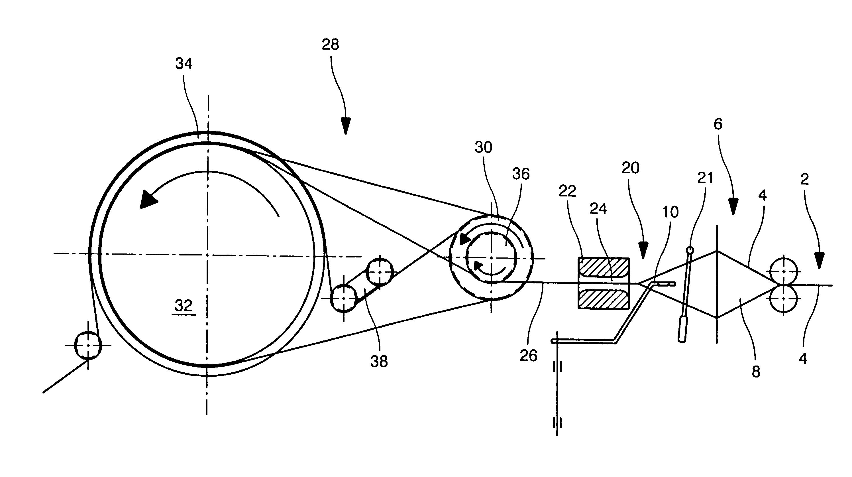
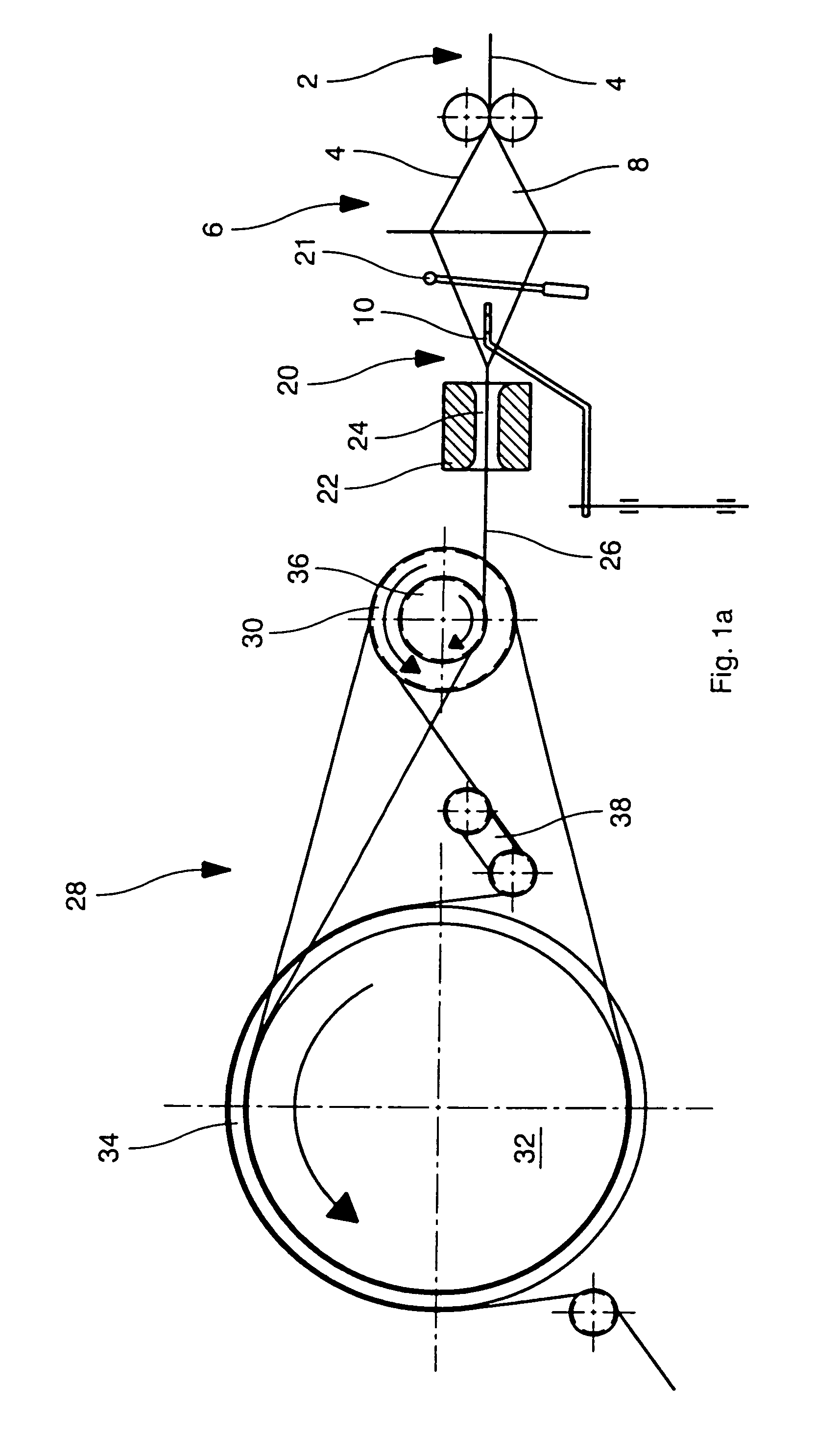
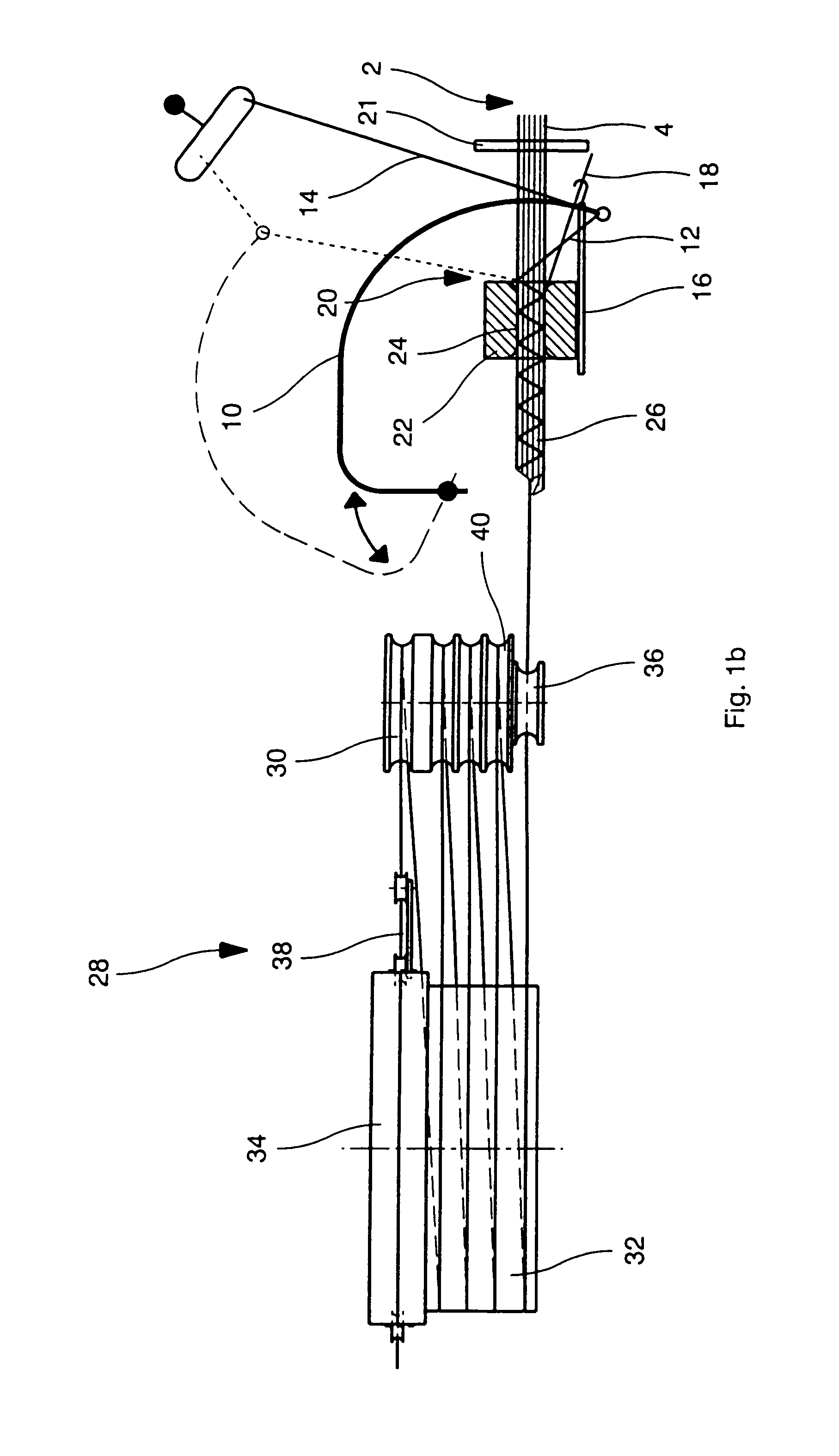
[0039]FIGS. 1a and 1b schematically illustrate a side view and a plan view of a weaving machine, which has a device 2 for supplying warp threads 4. By means of a shedding device 6, the warp threads 4 are opened to form a shed 8, so that a weft thread loop 12 of a weft thread 14 can be inserted into the shed 8 by means of a weft insertion needle 10. The weft thread loop 12 is tied off on the side facing away from the insertion side by means of a knitting needle 16. The weft thread loop 12 can be tied off using the weft thread loop which has already been inserted, but tying off preferably takes place with the aid of an auxiliary thread 18. Tying off advantageously takes place such that the inserted weft thread loops 12 are prevented from rippling. At the weaving station 20, the inserted and tied off weft thread loop is beaten up by means of a reed 21 and supplied to the cloth holder 22, which has a shaping opening 24, the opening cross section of which corresponds substantially to the...


PUM


Abstract

The loom contains a weaving station, at which warp yarns can be interwoven by means of at least one weft yarn, a device for supplying the warp yams, and a device for supplying the at least one weft yam. A shedding device for forming a shed from the warp yarns, and a weft insertion needle for inserting a weft yarn loop into the shed, are also present. The weft yam loop is tied off with a knitting needle and beaten with a reed. A take-down device serves to draw off the woven fabric that is produced. In order to produce a profiled woven article, the weaving station is assigned a fabric holder with a shaping aperture whose opening cross section corresponds substantially to the cross section of the profiled woven article that is to be produced with a round or polygonal cross section.

Description

[0001]This application claims priority of PCT application PCT / EP2009 / 004123 having a priority date of Jul. 15, 2008, the disclosure of which is incorporated herein by reference.TECHNICAL FIELD[0002]The invention relates to a weaving machine for producing a fabric having a profiled cross section, in particular a rope.BACKGROUND OF THE INVENTION[0003]Ropes are generally produced on laying machines or braiding machines; the disadvantage here is that these machines have limited capacity and enable only ropes of limited length.[0004]U.S. Pat. No. 2,130,636 describes a weaving machine, of the type mentioned initially, for producing a strip, that is a flat structure, the weaving station usually being assigned a cloth holder. The cloth holder serves exclusively for holding the strip fabric, which is already flat per se, and therefore has no influence at all on profile shaping. DE 20000593 describes a device for producing a bent strip, which is connected as an additional assembly downstream ...

Claims


Application Information

Patent Timeline
Patent Type & Authority Applications(United States)
IPC IPC(8): D03D35/00D03D41/00D03D49/20D03J1/22
CPCD03D35/00D03J1/223D03D49/20D03D41/004
Inventor LEPPLA, KLAUSANKLI, PHILIPPEGOOSSEN, BERNHARD
Owner TEXTILMA AG
Why Eureka
Try Eureka