Conducting wire structure and method of manufacturing a conducting wire core

a technology of conducting wire and core, which is applied in the direction of insulated conductors, flat/ribbon cables, cables, etc., can solve the problems of wasting resources, affecting a large portion of the metallic conductor in the center is useless, etc., to achieve the effect of increasing the conductive area of the core, reducing the cost, and speeding up the speed

Inactive Publication Date: 2011-06-30
INNOTRANS TECH
View PDF0 Cites 14 Cited by
  • Summary
  • Abstract
  • Description
  • Claims
  • Application Information

AI Technical Summary

Benefits of technology

[0007]The conducting wire structure according to the present invention includes at least one core and an insulation skin encasing outer edge of the core to form a conducting wire. The core contains a plurality of flattened conductors formed in a flattened cross section and stacked together. The flattened conductors are interposed by an insulation layer which bonds two neighboring flattened conductors, and then the bonded conductors are stacked to form the core in an integrated manner. The flattened conductors in the core can conduct an identical electric signal, hence the combined surface area of the flattened conductors can also transmit electric power or signals to maximize the conductive area of a single core. The present invention also provides a method to fabricate the core. The method includes procedures as follow: providing a plurality of flattened conductors with flattened cross sections through a flattened conductor fabrication means; coating an insulation layer on the surfaces of the flattened conductors through a coating means; stacking the flattened conductors coaxially to form a core. The flattened conductor fabrication means can form the flattened conductors from calendering conductors with any shapes or cutting a flattened conductor. By means of the present invention, the flattened conductors can be stacked to get maximum conductive surface area and fabricated at a lower cost and faster speed to produce a conducting wire of a higher electric conductivity.

Problems solved by technology

Under such a phenomenon, if the conducting wire still adopts the conventional round cross-section one, electric power merely passes through the surface of the conducting wire and a great portion of the metallic conductors in the center is useless and becomes a waste of resource.
While it provides a breakthrough over the conventional technique of round conductor wire and offers enhanced electric conduction capability, fabricating the scalene geometric section involves more complex processes than manufacturing the round conductor.
Moreover, different types of scalene geometric section have varying physical strengths and their capability to withstand external forces such as compression or bending also are different, and might even be inferior to the round conductor.
Taking into account of fabrication cost, speed and physical strength of the conductor body, its application is limited.
However, changing the form of the conducting wire incurs additional manufacturing difficulties and higher cost.

Method used


Image

  • Conducting wire structure and method of manufacturing a conducting wire core
  • Conducting wire structure and method of manufacturing a conducting wire core
  • Conducting wire structure and method of manufacturing a conducting wire core

Examples


Embodiment Construction

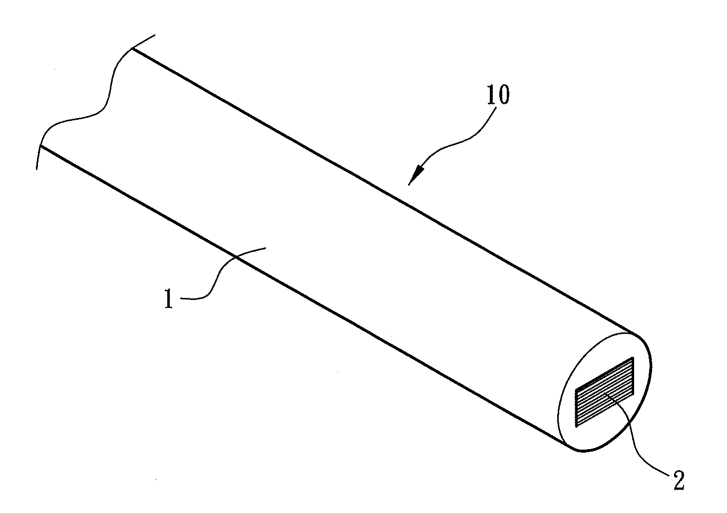
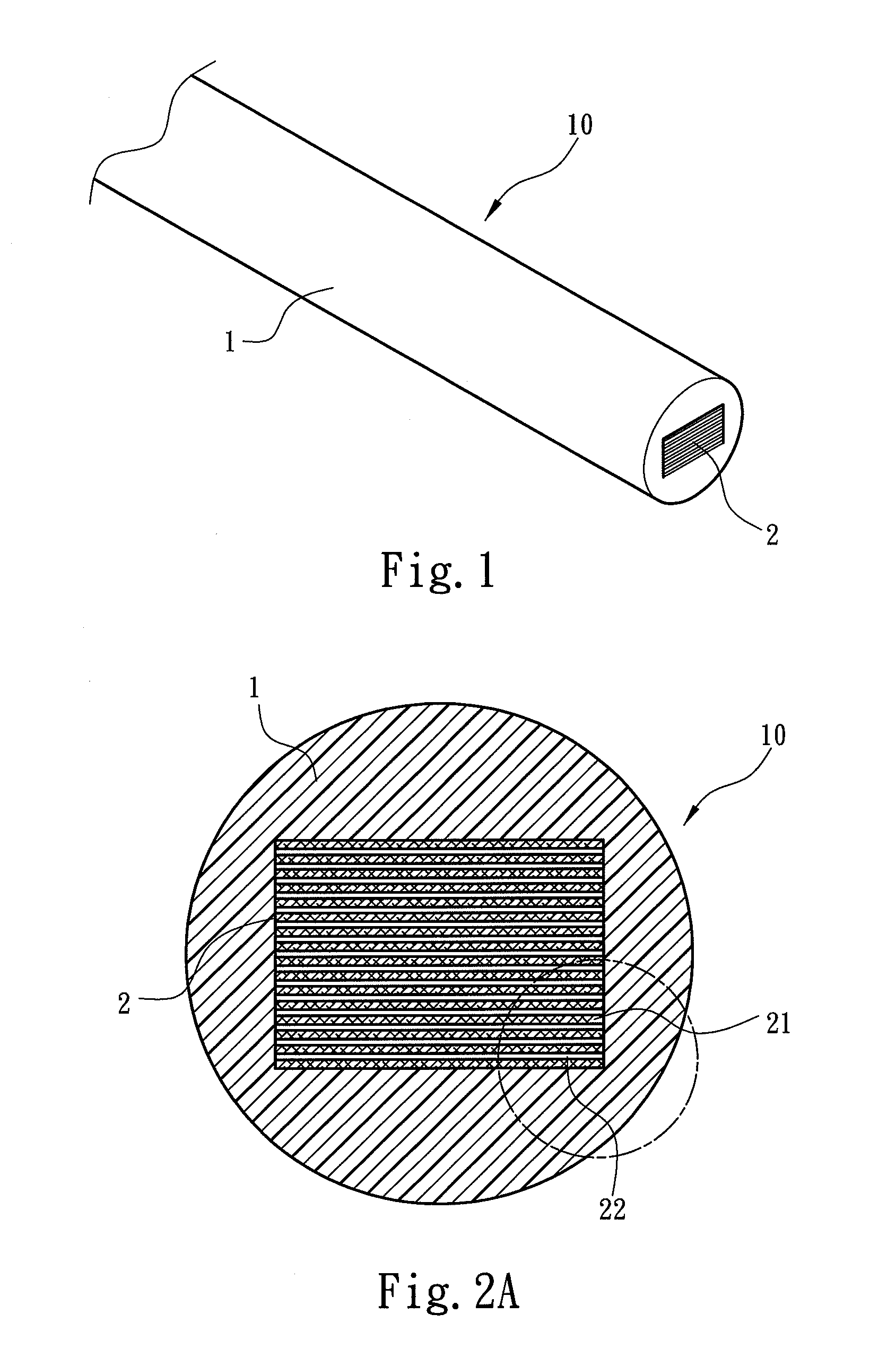
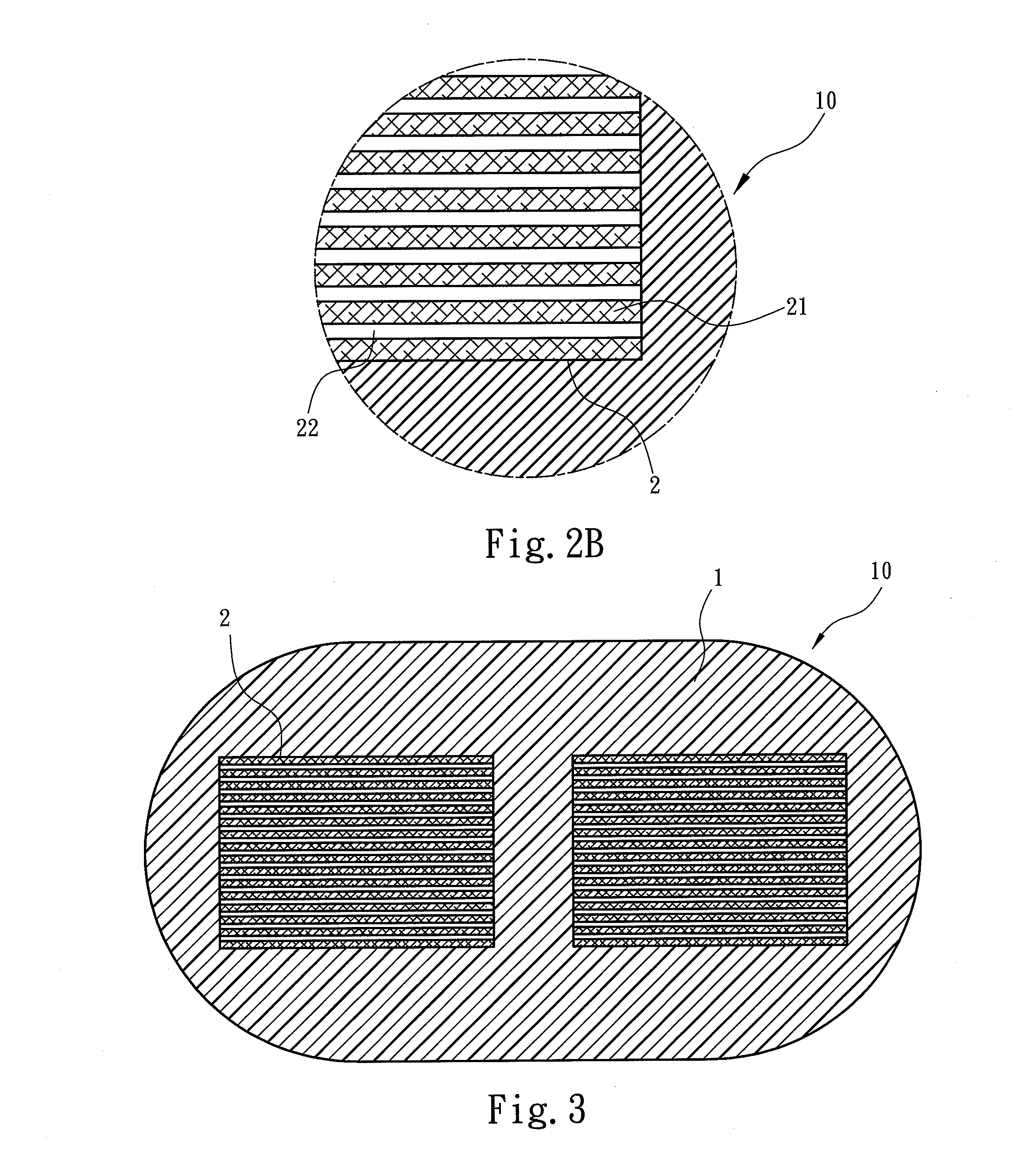
[0018]The present invention aims to provide a conducting wire structure and a method of manufacturing a core in the conducting wire. Referring to FIGS. 1 and 2A, a conducting wire 10 according to the present invention has a core 2 located inside. The core 2 contains a plurality of flattened conductors 21 each is formed in a flattened cross section and coated on the circumference with an insulation layer 22. The insulation layer 22 bonds the neighboring flattened conductors 21 to form the core 2. The flattened conductors 21 conduct an identical electric signal. FIG. 1 illustrates en embodiment in which the core 2 is encased by an insulation skin 1 to become a commonly used insulated conducting wire. As the core 2 is formed by stacking a plurality of flattened conductors 21, in addition to the circumference of the core 2, the spaced flattened conductors 21 in the core 2 also provide surface area to conduct electric power. Hence the portion of electric conduction in the core 2 is the s...


PUM

PropertyMeasurementUnit
circumferenceaaaaaaaaaa
conductiveaaaaaaaaaa
electricaaaaaaaaaa

Abstract

A conducting wire structure and a method of manufacturing a conducting wire core, the conducting wire comprises at least one core and an insulation skin encasing the core. The core is formed by stacking a plurality of flattened conductors with flattened cross sections interposed by an insulation layer. The insulation layer bonds two neighboring flattened conductors to form the core in an integrated manner. The flattened conductors can conduct an identical electric signal. Thus the surface area of the flattened conductors can transmit electric power or signal to maximize conductive area of one core. The method of manufacturing a core includes: providing a plurality of flattened conductors with flattened cross sections through a conductor flattened fabrication means; coating an insulation layer on the surface of the flattened conductors through a coating means; and stacking the flattened conductors coaxially to form a core. Thus conductive surface area can be maximized.

Description

FIELD OF THE INVENTION[0001]The present invention relates to a conducting wire structure and a method of manufacturing a conducting wire core and particularly to a conducting wire containing a special conductor structure.BACKGROUND OF THE INVENTION[0002]Ever since human being started using electric power, how to transmit the electric power is a subject constantly pursued by mankind. In the early development stage of electrical science, Ohm's law was discovered. Ohm's law can be summed up in an equation: V=IxR, where V represents voltage, R represents resistance, and I represents current passing through the resistance R when the voltage V is applied thereon. Theoretically, whether electric power can pass through an object depends on the resistance of the object. According to Ohm's law, current I flows through a path of the lowest resistance. Hence applying a voltage on an object, current tends to flow through the portion where the resistance is the lowest. In order to reduce electric...

Claims


Application Information

Patent Timeline
Patent Type & Authority Applications(United States)
IPC IPC(8): H01B7/08H01B13/00H01B13/016
CPCH01B7/303H01B7/0018
Inventor HU, JEN-YAO
Owner INNOTRANS TECH
Why Eureka
Try Eureka