Arrangement for cable guiding and a wind turbine using such arrangement

a technology for wind turbines and cable guiding, which is applied in the direction of motors, engine fuctions, conductors, etc., can solve the problems of increasing the thickness, weight and cost of high voltage cables, and increasing the weight and cost of cables. , to achieve the effect of reducing the risk

Active Publication Date: 2011-06-30
VESTAS WIND SYST AS
View PDF1 Cites 8 Cited by
  • Summary
  • Abstract
  • Description
  • Claims
  • Application Information

AI Technical Summary

Benefits of technology

[0024]The pulley system may comprise a pulley being moveable between a first and a second position for controlling the free length of the at least one second cable. By controlling the free length of the at least one second cable, the risk is reduced that the twisting of the cables results in the cables get entangled. When the at least one second cable unwinds, the pulley system is adapted to control the free length of the at least one second cable, i.e. to control the slack.
[0025]The pulley may be moveable along a slot. By the pulley being movable between different positions, it is possible to control the free length of the at least one second cable, such that entanglement is avoided.
[0026]Said pulley may be moveable between the first and second position when turning said at least one second cable in view of the first guide member. When the nacelle turns, the at least one second cable is wound on the envelope surface of the first tubular housing. During the winding the pulley moves to a second position, compensating the reduced free length of the at least one second cable. When the at least one second cable unwinds, the pulley moves back to the first position in order to compensate for the now increased free length of the at least one second cable.

Problems solved by technology

To avoid disturbances from the high voltage cable, the latter must be provided with an outer shielding, thereby increasing its thickness, weight and cost.
Due to the extra shielding of the high voltage cable, which is required for avoiding disturbances on the additional cables arranged in the tower, the high voltage cable becomes expensive and heavy.
Additionally, all cables must be made with an extra length in order to allow for the twisting due to the turning of the nacelle, which additionally adds to the weight and cost of the cables.

Method used


Image

  • Arrangement for cable guiding and a wind turbine using such arrangement
  • Arrangement for cable guiding and a wind turbine using such arrangement
  • Arrangement for cable guiding and a wind turbine using such arrangement

Examples


first embodiment

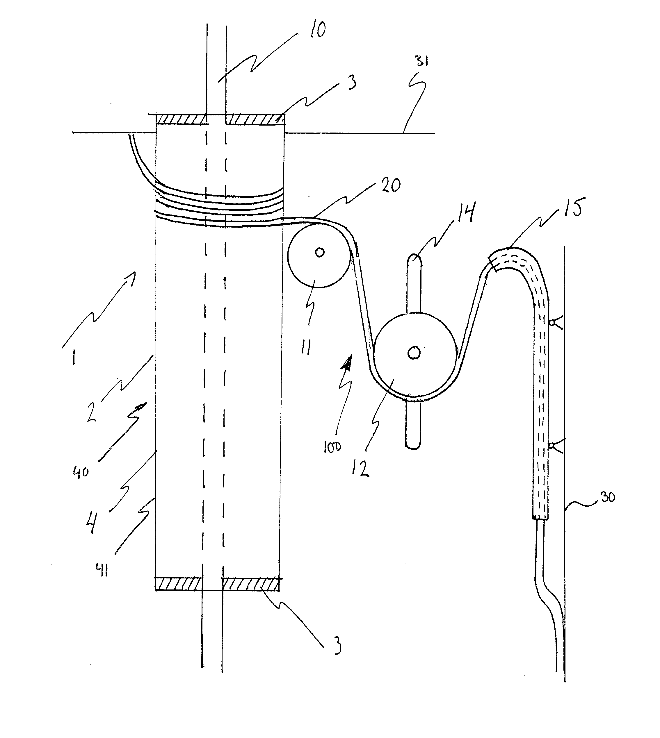
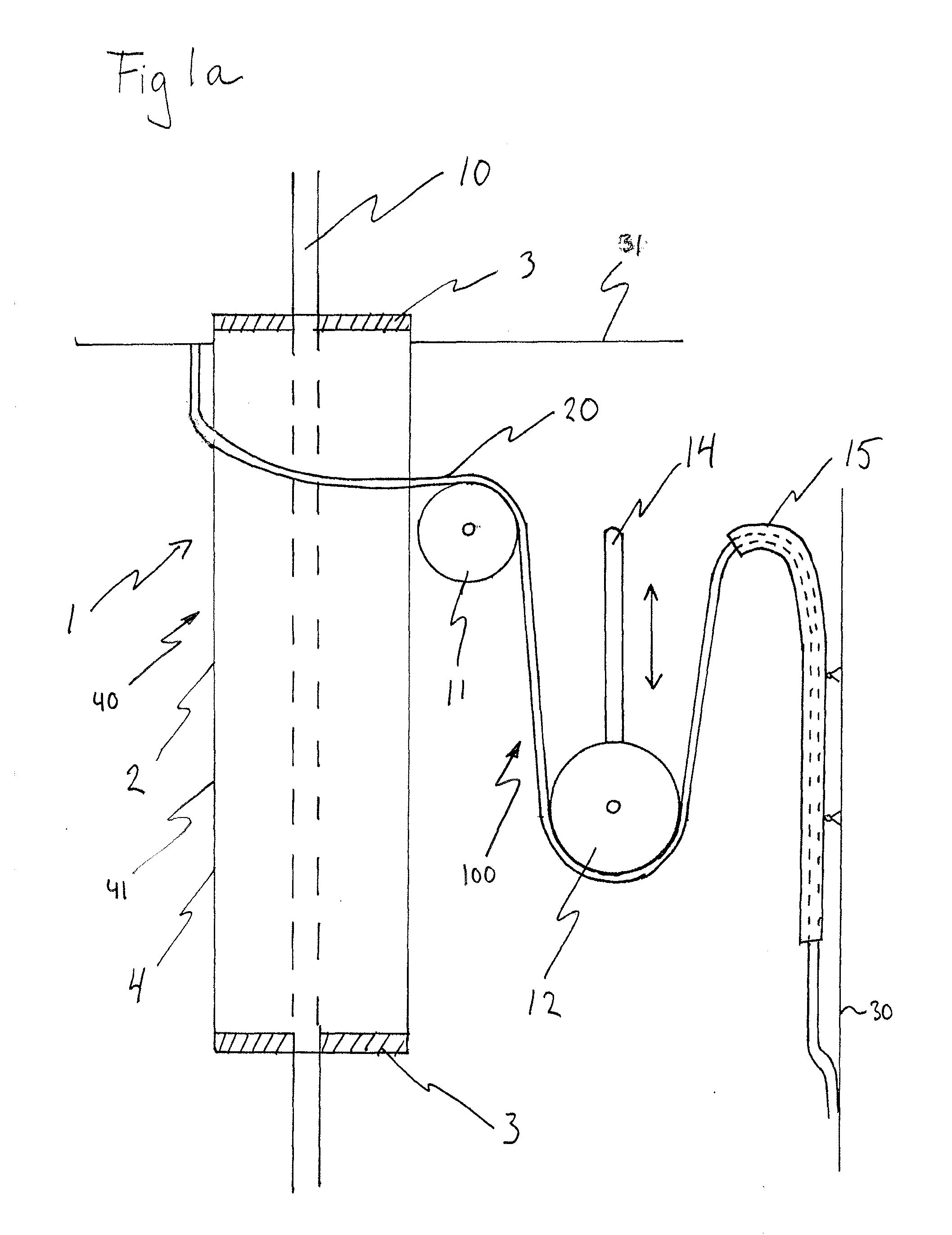
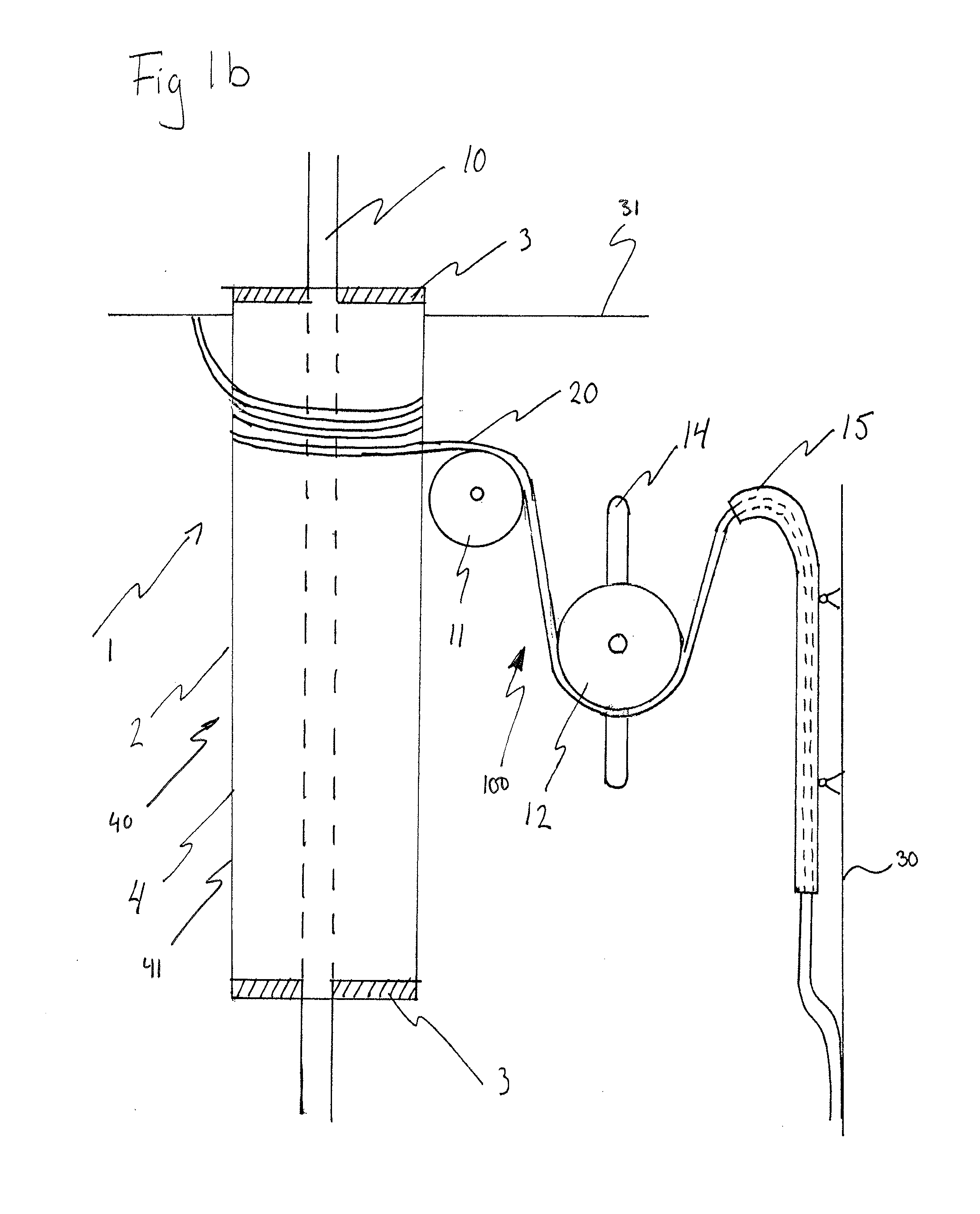
[0045]With reference to FIGS. 1a and 1b, an arrangement 1 according to the invention will be described. The arrangement 1 is arranged in an upper section 31 of a wind turbine tower 30. The tower 30 is extending from the ground to a nacelle of the wind tower. A first cable 10, such as a high voltage cable, is extending from the nacelle towards the ground through the tower 30 in a vertical direction. At least one second cable 20 is also extending from the nacelle to the ground. The at least one second cable 20 may be a signal cable, or any other cable arranged in the tower 30.

[0046]The arrangement 1 comprises a first guide member 40, in this embodiment in the form of a first tubular housing 2. The first tubular housing 2 extends inside a part of the tower 30 in a vertical direction.

[0047]The first tubular housing 2 encloses the first cable 10. The first tubular housing 2 is provided with supporting elements 3 ensuring that a radial distance is formed between the envelope surface 4 of ...

second embodiment

[0056]FIG. 2 discloses the arrangement 1. In this embodiment, the arrangement 1, arranged in the tower as previously described, comprises the first guide member 40 and a second guide member 50. The first guide member 40 is in form of the first tubular housing 2. The tubular housing 2 encloses the first cable 10, and the at least one second cable 10 is extending along the upper portion of envelope surface 4 of the first tubular housing 2, as previously disclosed with reference to FIGS. 1a and 1b.

[0057]The second guide member 50 is in form of a second tubular housing 21. The second tubular housing 21 is arranged adjacent the first tubular housing 2 in the upper section 31 of the wind turbine tower 30 and is extending in the vertical direction. The envelope surface 22 of the second tubular housing 21 forms a second guide surface 51. The first and the second tubular housings 2, 21 are interconnected by a mechanical coupling device 23, such that the first and the second tubular housings...

third embodiment

[0061]With reference to FIG. 3 and FIG. 4, the present invention will be described. The arrangement 1 according to this embodiment comprises a first guide member 40 in form of a number of discs 6. A single disc 6 will be described in more detail with reference to FIG. 4. Preferably, a plurality of discs 6 forms the first guide member 40.

[0062]The first guide member 40 encloses the first cable 10. The first guide member 40 is adapted to receive the first cable 10 through a central portion 8 of the first guide member 40. The distance between the central portion 8 of the first guide member 40 and the outer periphery 17 of the first guide member 40 ensures shielding of the first cable 10. Thus, the shielding is achieved by a combination of air and material in the first guide member 40.

[0063]The outer periphery 17 of the first guide member 40 is provided with recesses 9 adapted to receive a number of clips 7. In the shown embodiment, the first guide member 40 comprises a plurality of rec...


PUM

PropertyMeasurementUnit
diameteraaaaaaaaaa
lengthaaaaaaaaaa
distanceaaaaaaaaaa

Abstract

The present invention relates to an arrangement (1) for cable guiding, comprising a first guide member (40) adapted to enclose a first cable (10) along at least a part of the length of said first cable. The first guide member (40) has an outside surface adapted to form at least one first guide surface (41) supporting at least one second cable (20) along at least a part of the length of said first cable. The present invention further relates to a wind turbine comprising such an arrangement and to the use of such an arrangement.

Description

TECHNICAL FIELD[0001]The present invention generally relates to an arrangement for cable guiding in a wind turbine tower. The arrangement is adapted to provide sufficient shielding of e.g. a high voltage cable, and facilitate turning or twisting of the cables due to the turning of the nacelle of the wind turbine. The arrangement, comprising a guide member, is adapted to guide a first cable and at least one second cable, extending from the nacelle of the wind turbine to the ground through the interior space of the tower, along an upper section of the tower. The present invention further relates to a wind turbine comprising such an arrangement and to use of such an arrangement.BACKGROUND OF THE INVENTION[0002]A wind turbine generally comprises a tower, a nacelle, at least one blade and a yaw bearing arranged between the tower and the nacelle. A high voltage cable is drawn from a generator arranged in the nacelle, down to the ground through the interior space of the tower. Generally, t...

Claims


Application Information

Patent Timeline
Patent Type & Authority Applications(United States)
IPC IPC(8): H01B7/00
CPCB66D1/36B66D1/7405F03D11/00Y02E10/726F05B2260/30H02G11/02Y02E10/722F03D11/0066F03D80/00F03D80/85Y02E10/72
Inventor OLLGAARD, BORGE
Owner VESTAS WIND SYST AS
Why Eureka
Try Eureka