Method and apparatus for electric isolation transmission

a technology of electric isolation and transmission device, which is applied in the direction of electrical apparatus, ac-ac conversion, power conversion system, etc., can solve the problems of difficult to improve power transmission efficiency, difficult to make the thickness of the conventional isolation transformer (i.e. the thickness of the device) thinner, and poor performance of the electric isolation between the primary side and the secondary side, etc., to achieve the effect of increasing the transmission efficiency of the power source, high efficiency and small siz

Active Publication Date: 2011-06-30
FSP POWERLAND TECH INC NANJING +1
View PDF5 Cites 17 Cited by
  • Summary
  • Abstract
  • Description
  • Claims
  • Application Information

AI Technical Summary

Benefits of technology

[0028]Moreover, the apparatus can be applied to electric products with light-weight and high efficiency requirements in which an isolation transformer is installed. For example, the electric products can be power adapters or power sources of CCFL backlight modules of LCD flat panel televisions. In addition, the apparatus can be applied to wireless transmission. Since coupling capacitors are utilized, this can effectively increas

Problems solved by technology

This results in a worse performance of the electric isolation between the primary side and the secondary side.
Accordingly, it is impossible to make the size of the convention

Method used


Image

  • Method and apparatus for electric isolation transmission
  • Method and apparatus for electric isolation transmission
  • Method and apparatus for electric isolation transmission

Examples


Embodiment Construction

[0046]The detailed descriptions pertinent to embodiments of the present invention are listed in the following in conjunction with related figures. In addition, safety capacitors are used as examples in the following embodiments but are merely used for illustrative purposes; this is not meant to be a limitation of the present invention.

[0047]In the embodiments, by using capacitive elements such as capacitors to isolate, the leakage current Iearth (Iearth=Ie1+Ie2) in the circuitry loops in which the currents Ie1 and Ie2 pass through, the leakage current Iearth can be suppressed / decreased to become smaller than the current ITC0 to thereby implement isolation between a primary side (i.e. the first side) and secondary side (i.e. the second side) of the transformer as long as the capacitances of the capacitors CS1 and CS2 are guaranteed to be small enough. In addition, a testing circuit ZTC as shown in FIG. 3 is utilized in practical tests. For example, the design of the resistances and c...


PUM


Abstract

A method and apparatus used for electric isolation transmission are provided. The method includes: providing an isolation transmission circuit having at least one capacitor; and implementing electric isolation between the primary side and secondary side, and suppressing leakage currents generated between the primary side and secondary side and transmitting power. The apparatus includes the isolation transmission circuit that is manufactured by capacitor(s). The apparatus can be applied to light-weight power sources providing AC/DC outputs with high efficiency, adapters, or related products. In addition, the apparatus has a reduced size and higher power transmission efficiency.

Description

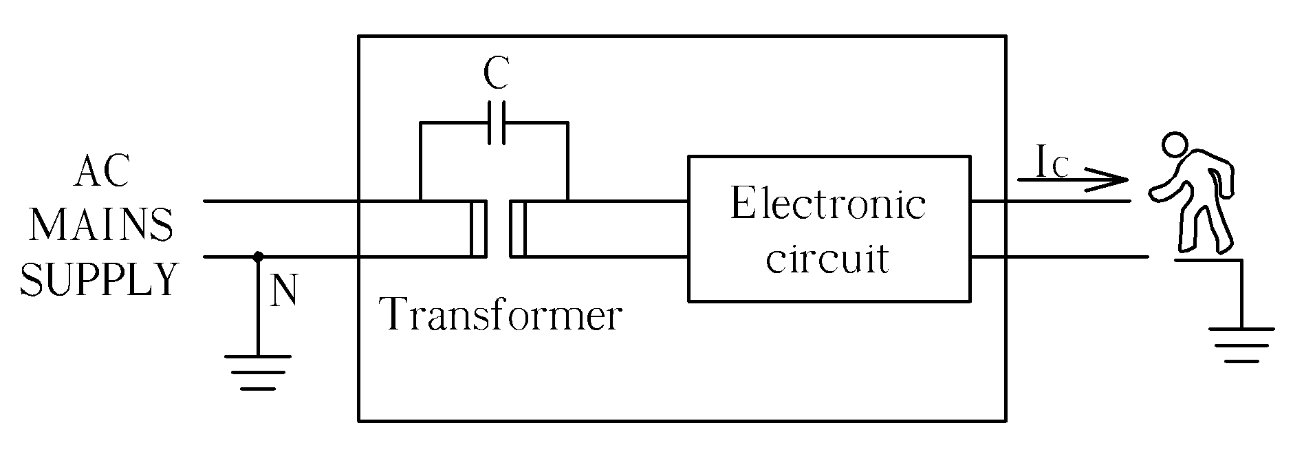
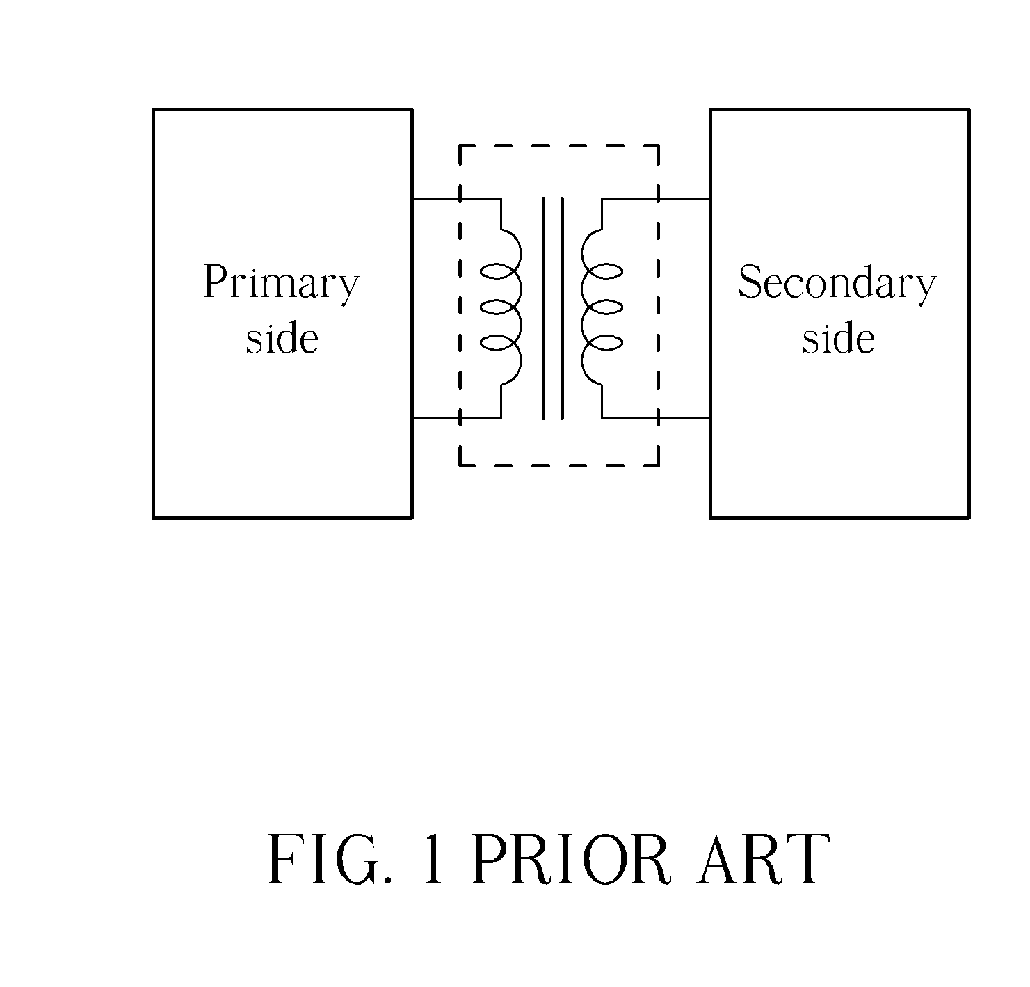
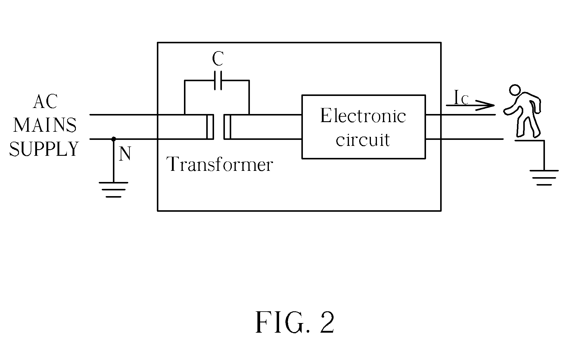
BACKGROUND OF THE INVENTION[0001]1. Field of the Invention[0002]The present invention relates to an electric isolation transmission scheme, and more particularly to a method and an apparatus used for electric isolation transmission.[0003]2. Description of the Prior Art[0004]Please refer to FIG. 1, which illustrates a diagram of a conventional power system. The conventional power system utilizes an isolation transformer to implement electric isolation between the primary side and the secondary side. Please refer to FIG. 2, which shows a diagram illustrating a leakage current (i.e. a touch current) due to the isolation transformer in the conventional power system. As shown in FIG. 2, the driving source of the leakage current is a power source having a frequency of 50 / 60 Hz. In practical applications, parasitic capacitance CK exits between the primary side and the secondary side of the isolation transformer. This results in a worse performance of the electric isolation between the prim...

Claims


Application Information

Patent Timeline
IPC IPC(8): H02M5/45
CPCH02M5/08H02M5/00
Inventor SUN, JU-LUZHU, JING-PENGXU, MING
Owner FSP POWERLAND TECH INC NANJING
Why Eureka
Try Eureka