Temperature monitoring for circuit breakers

a technology of circuit breakers and temperature monitoring, applied in the direction of pulse techniques, power conversion systems, instruments, etc., can solve the problems of inability to accurately calculate the temperature of each individual power switch, large temperature differences in various locations of the cooling body, etc., to improve the use of the power switch, accurate calculation of the temperature of each individual, and the effect of reducing power reserv

Active Publication Date: 2011-06-30
BAUMULLER NURNBERG GMBH
View PDF9 Cites 5 Cited by
  • Summary
  • Abstract
  • Description
  • Claims
  • Application Information

AI Technical Summary

Benefits of technology

[0011]With the method of prior art as described above it is not possible to accurately calculate the temperature of each individual power switch with the aid of a temperature model and to protect the power switch against temperature, as a homogeneity of the temperature distribution that does not exist in practice is always assumed. Contrary to this it is possible with the invention to realise the advantage of an improved use of the power switch thanks to the precise thermic monitoring of the same, e.g. with a much lower power reserve. it is possible with the invention to very accurately detect the temperatures of a number of power switches, for example those of a converter with very large mechanical dimensions and / or for an operation at a very small output frequency or basic motor vibration frequency with a minimum of extra effort by way of temperature sensors, on the basis of which the thermic capacity is used more effectively.

Problems solved by technology

In fact the temperature differences between the inlet and outlet air streams are higher in particular under greater load of the power switch, or even very large in the converter formed with the same, as the correspondingly high losses must be exported via the cooling medium.
In addition the cooling body also shows large temperature differences in various locations and in various areas.
With the method of prior art as described above it is not possible to accurately calculate the temperature of each individual power switch with the aid of a temperature model and to protect the power switch against temperature, as a homogeneity of the temperature distribution that does not exist in practice is always assumed.

Method used


Image

  • Temperature monitoring for circuit breakers
  • Temperature monitoring for circuit breakers
  • Temperature monitoring for circuit breakers

Examples


Embodiment Construction

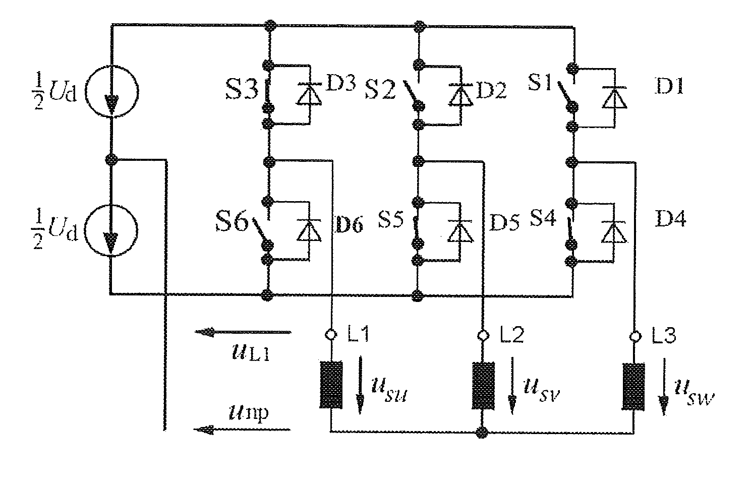
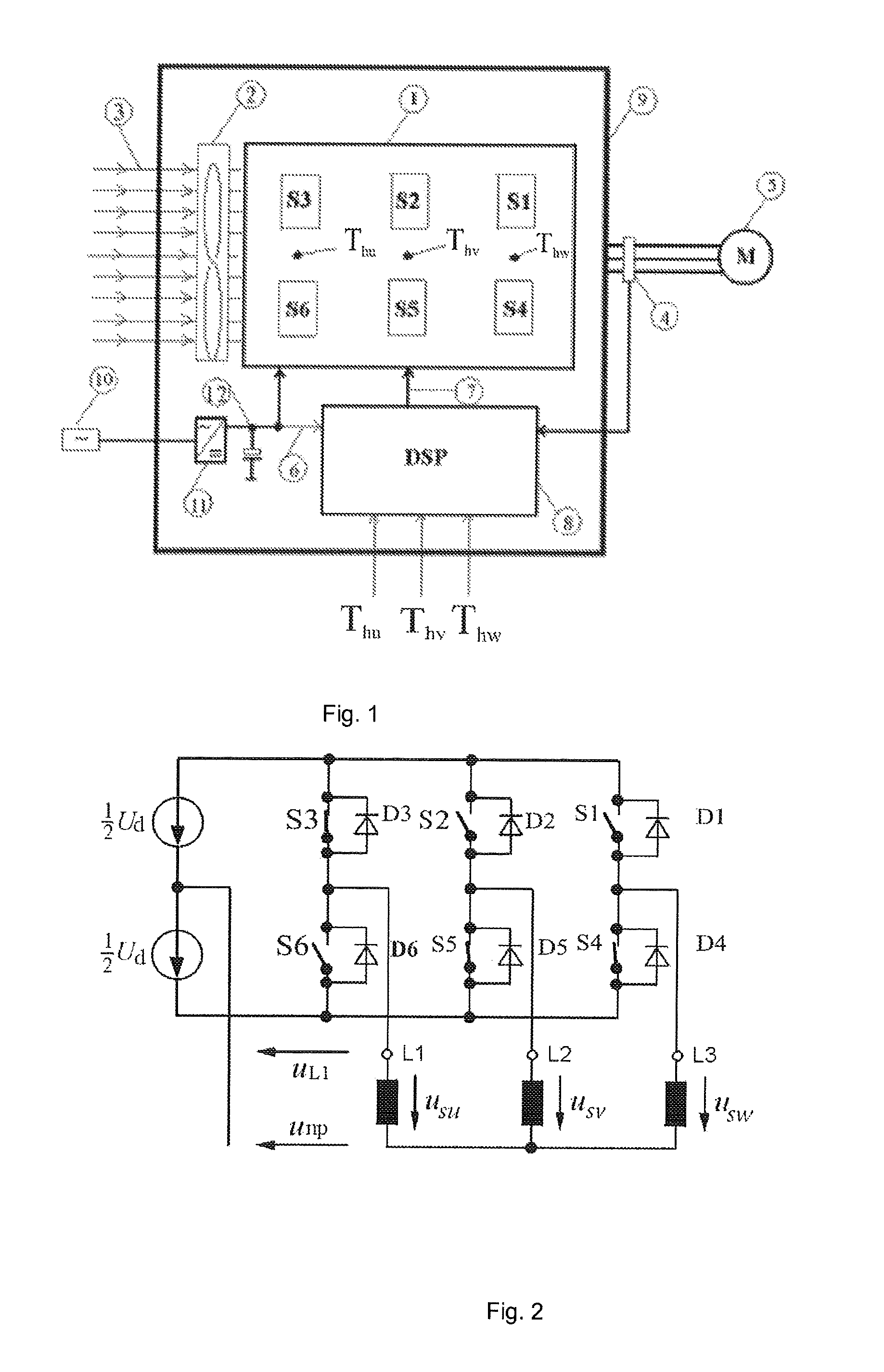
[0021]According to FIG. 1 six power semi-conductor switches S1-S6 are fitted directly onto a somewhat oblong rectangular cooling body. They are arranged in two parallel rows S1-S3, e.g. S4-S6 extending side by side, which each extend along one half of the cooling body and in a longitudinal direction of the same. In FIG. 2 the detailed assembly of the switches S1-S6 is shown as it is generally known to the expert world (see for example the SEMIKRON company information mentioned above; pages 68, 69 and 139). It is clear in particular that each power switch S1, . . . S6 has been allocated a free, e.g. return diode D1, . . . D6. Between two power switches S1, S4; S2, S5; S3, S6 switched in series and each generating a phase U, V, W of the three-phase current system a sinus shaped alternating current is measured and for example supplied to the coils L1, L2, L3 of the rack of a three-phase motor.

[0022]According to FIG. 1 a current measurement 4 is carried out at the three phase strands of...


PUM


Abstract

Method for detecting and/or monitoring the temperatures of at least two electronic power switches, in particular semi-conductor power switches that are coupled with or arranged on a common cooling body, whereby a temperature detection and/or monitoring is carried out by means of a temperature model each allocated to a switch, in which switch and operating parameters as well as temperature measurement values are processed for calculating the temperature and/or a temperature difference in the relevant switch, whereby a temperature measurement value from a temperature sensor is used as an input parameter for the temperature model, the same being centrally positioned between at least two switches and standing in a heat conducting connection with the cooling body.
Electronic temperature emitting power switch arrangement, in particular a transformer for electric drives or other power rectifiers for carrying out the method according to one of the preceding Claims, with two or more switches, in particular semi-conductor power switches coupled with or arranged on a common cooling body, and with a calculator suitable for implementing and executing a temperature model by means of one switch each, and interfaces for receiving signals representing switch and operating parameters as well as temperature measurement values in order to calculate the temperature and/or a temperature difference within the relevant switch by means of the temperature model, whereby a temperature sensor is positioned centrally between the two or between two switches each, the same being coupled in a heat conducting way with the cooling body and with the output side of the calculator.

Description

BACKGROUND OF THE INVENTION[0001]The invention concerns a method for detecting and / or monitoring the temperatures of at least two electronic power switches manufactured in particular from a semi-conductor material. In addition the two switching modules are coupled with, e.g. positioned on a common cooling body. The temperature detection and / or monitoring is carried out by means of a temperature model, each of which is associated with one of the switches or switching modules. In the temperature model associated with one of the switches switching and operating parameters are processed in order to calculate the temperature and / or a temperature difference within the relevant switches.[0002]The invention further concerns a temperature emitting electronic power switch assembly that can in particular consists of a converter for electric drives or another power converter. This arrangement is suitable for carrying out the said method and is equipped with two or more switches, in particular p...

Claims


Application Information

Patent Timeline
Patent Type & Authority Applications(United States)
IPC IPC(8): H02M7/217H03K17/687H02M7/5387
CPCG05D23/1935H02M7/5387H02M7/53871H02M7/003
Inventor JIANG, JINSHENG
Owner BAUMULLER NURNBERG GMBH
Why Eureka
Try Eureka