Optical Disk Drive and Method for Performing Layer Jumps

Inactive Publication Date: 2011-06-30
MEDIATEK INC
View PDF18 Cites 0 Cited by
  • Summary
  • Abstract
  • Description
  • Claims
  • Application Information

AI Technical Summary

Benefits of technology

[0009]Similarly, when the optical disk drive performs a layer jump to move the laserbeam from the BD-ROM layer to the BD-RE / R layer, if the initial DPD method corresponding to BD-ROM layer is used (without adjustment) to generate a tracking error signal corresponding to the BD-RE / R layer, the tracking error signal would have a small amplitude, and comprise a lot of noise, and would not be able to be used for correctly moving the laserbeam along a track of the BD-RE / R layer. Thus, a method for generating a correct tracking error signal when a layer jump is performed is required.
[0042]While the invention has been described by way of example and in terms of preferred embodiment, it is to be understood that the invention is not limited thereto. To the contrary, it is intended to cover various modifications and similar arrangements (as would be apparent to those skilled in the art). Therefore, the scope of the appended claims should be accorded the broadest interpretation so as to encompass all such modifications and similar arrangements.

Problems solved by technology

If the first layer and the second layer are of different types, the method initially used for generating a tracking error signal corresponding to the first layer may be not suitable for generating a tracking error signal corresponding to the second layer.
When an optical disk drive performs a layer jump to move a laserbeam from the BD-RE / R layer to the BD-ROM layer, if the initial DPP method corresponding to the BD-RE / R layer is used (without adjustment) to generate a tracking error signal corresponding to the BD-ROM layer, the tracking error signal would have a small amplitude, and comprise a lot of noise, and would not be able to be used for correctly moving the laserbeam along a track of the BD-ROM layer.
Similarly, when the optical disk drive performs a layer jump to move the laserbeam from the BD-ROM layer to the BD-RE / R layer, if the initial DPD method corresponding to BD-ROM layer is used (without adjustment) to generate a tracking error signal corresponding to the BD-RE / R layer, the tracking error signal would have a small amplitude, and comprise a lot of noise, and would not be able to be used for correctly moving the laserbeam along a track of the BD-RE / R layer.

Method used


Image

  • Optical Disk Drive and Method for Performing Layer Jumps
  • Optical Disk Drive and Method for Performing Layer Jumps
  • Optical Disk Drive and Method for Performing Layer Jumps

Examples


Embodiment Construction

[0026]The following description is of the best-contemplated mode of carrying out the invention. This description is made for the purpose of illustrating the general principles of the invention and should not be taken in a limiting sense. The scope of the invention is best determined by reference to the appended claims.

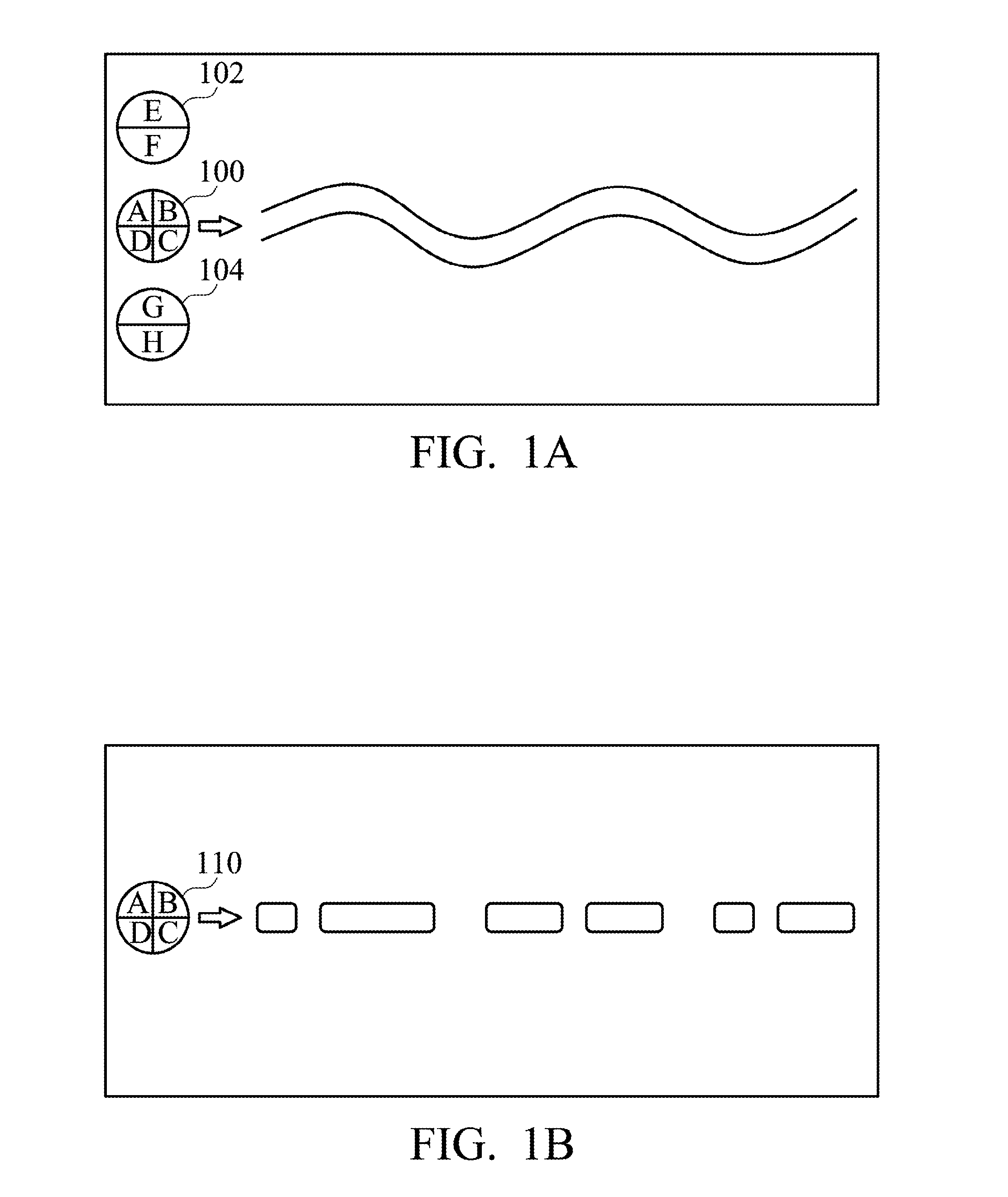
[0027]Referring to FIG. 1A, a schematic diagram for generating a tracking error signal according a differential push-pull (DPP) method is shown. An optical disk drive projects a main-beam 100 and two sub-beams 102 and 104 on a track of a BD-RE layer of a blu-ray disk. A groove on the BD-RE layer forms the track. The main-beam 100 is projected on the groove of the track, and the two side-beams 102 and 104 are projected on the two sides of the groove. Four photodetectors respectively detect signal strength of a portion of the reflection of the main-beam 100 to obtain signals A, B, C, and D. Two photodetectors detect signal strength of the reflection of the sub-beam 102 t...


PUM


Abstract

The invention provides a method for performing a layer jump of a disk. First, a tracking error generation method is determined according to a layer type of a target layer when the layer jump is performed. A tracking error signal is then generated according to the tracking error generation method.

Description

CROSS REFERENCE TO RELATED APPLICATIONS[0001]This application claims the benefit of U.S. Provisional Application No. 61 / 290,979, filed on Dec. 30, 2009, the entirety of which is incorporated by reference herein.BACKGROUND OF THE INVENTION[0002]1. Field of the Invention[0003]The invention relates to optical disk drives, and more particularly to tracking operations of optical disk drives.[0004]2. Description of the Related Art[0005]A multi-layer disk comprises a plurality of layers for storing data. Multi-layer disks can be divided into two categories. In one category, the type of the layers of a multi-layer disk for storing data is the same. For example, a BD-ROM dual-layer disk has two BD-ROM layers, a BD-RE dual-layer disk has two BD-RE layers, and a BD-R dual-layer disk has two BD-R layers. In another category, the type of the layers of a multi-layer disk for storing data is different. For example, a BD Inter-Hybrid disk comprises a BD-ROM layer and at least one DVD-ROM layer. A B...

Claims


Application Information

Patent Timeline
IPC IPC(8): G11B20/10
CPCG11B7/00736G11B7/08511G11B2007/0013G11B7/0906G11B7/0903
Inventor HSIN, KUO-TINGHUANG, CHAO-MING
Owner MEDIATEK INC
Why Eureka
Try Eureka