Method for Determining Updated Filter Coefficients of an Adaptive Filter Adapted by an LMS Algorithm with Pre-Whitening

a filter coefficient and algorithm technology, applied in the field of system identification, can solve the problems of inability to perform new measurements for every change, inability to accurately estimate the effect of changes, and inability to achieve accurate approximation. the effect of accuracy and decrease of error between the actual and the modeled outputs

Active Publication Date: 2011-06-30
GUANGDONG OPPO MOBILE TELECOMM CORP LTD
View PDF13 Cites 11 Cited by
  • Summary
  • Abstract
  • Description
  • Claims
  • Application Information

AI Technical Summary

Benefits of technology

[0004]An unknown linear system can be completely characterized by its impulse response. However, since most real-world systems have infinite impulse responses (i.e. an impulse response with infinite length), it is common practice to model such systems using a finite-length approximation of the infinite impulse response. Because such finite approximation cannot exactly model a system having an infinite impulse response, the output behavior of the real-world system and of the model with finite approximation typically differ when the real-world system and the model are stimulated by the same input signal. FIG. 1 illustrates such modeling of an unknown system 1 by a system model 2. Both unknown system 1 and system model 2 are stimulated by the same input signal-. For determining an error between the actual and modeled outputs, the output response of system model 2 is...

Problems solved by technology

When the accuracy of approximation increases, the error between the actual and the modeled outputs decreases.
While this method can be very effective, it becomes less attractive if the...

Method used


Image

  • Method for Determining Updated Filter Coefficients of an Adaptive Filter Adapted by an LMS Algorithm with Pre-Whitening
  • Method for Determining Updated Filter Coefficients of an Adaptive Filter Adapted by an LMS Algorithm with Pre-Whitening
  • Method for Determining Updated Filter Coefficients of an Adaptive Filter Adapted by an LMS Algorithm with Pre-Whitening

Examples


first embodiment

[0086]FIG. 7 illustrates a first embodiment, with a normalizing factor being transmitted from an LPC whitening filter to an adaptive coefficient update stage;

second embodiment

[0087]FIG. 8 illustrates a second embodiment, with a normalizing factor being transmitted from an LPC whitening filter to an adaptive coefficient update stage and pre-whitening being outside of the main signal path;

[0088]FIG. 9 illustrates an adaptive equalizer as a first application;

[0089]FIG. 10 illustrates an adaptive echo canceller as a second application;

[0090]FIG. 11 illustrates a feedback adaptive noise control system as a third application;

[0091]FIG. 12 shows a first simplified version of the third application in FIG. 11; and

[0092]FIG. 13 shows a second simplified version of the third application in FIG. 11.

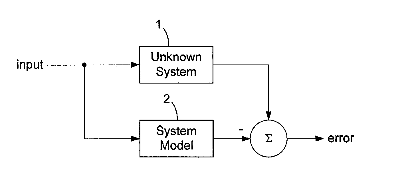
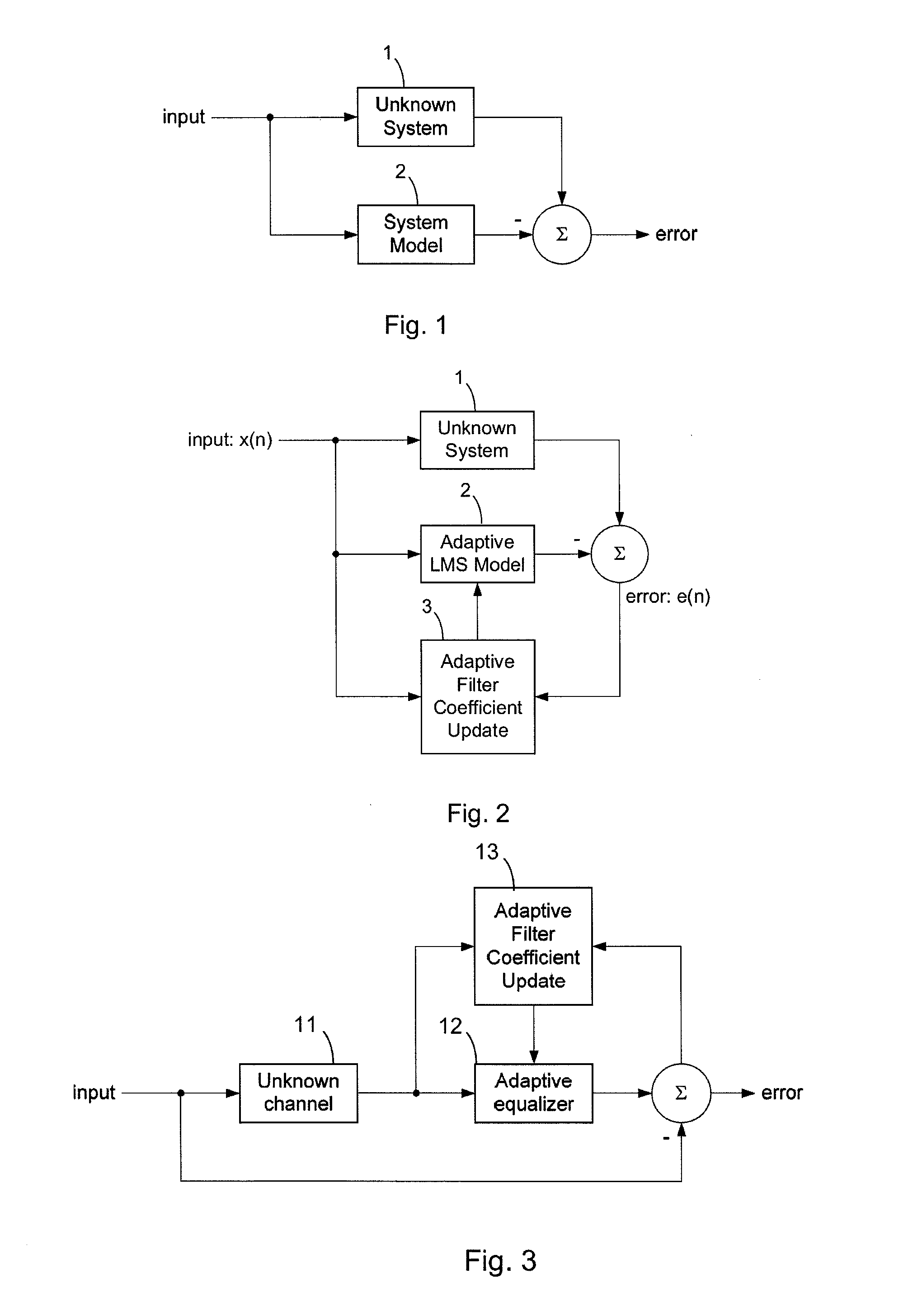
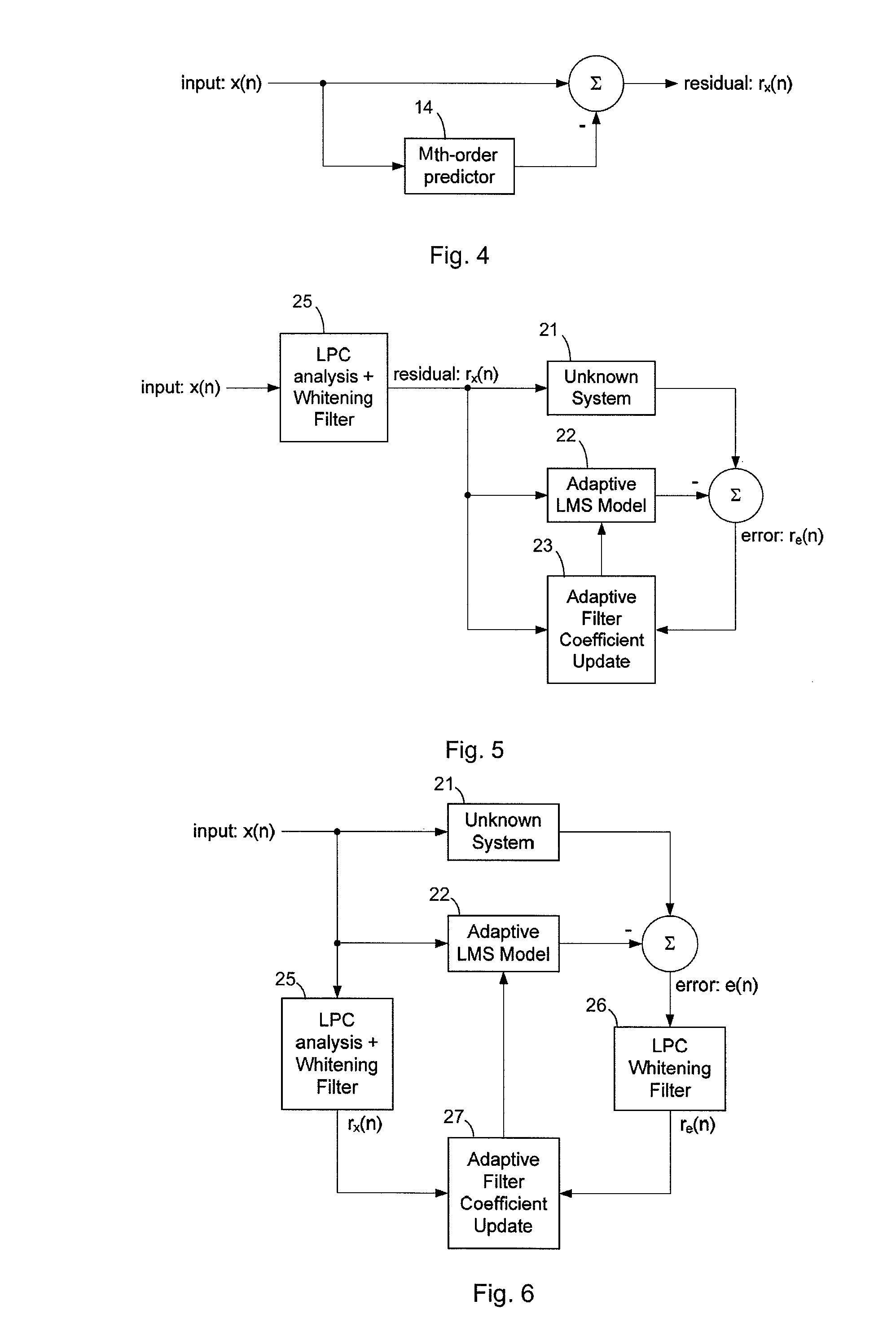
[0093]FIGS. 1-6 were already discussed above.

[0094]FIG. 7 illustrates a first embodiment of the invention. The first embodiment is similar to the configuration in FIG. 5. Figurative elements in FIG. 5 and FIG. 7 denoted by the same reference signs are basically the same. Moreover, the remarks to FIG. 5 are basically also applicable to FIG. 7.

[0095]In FIG. 7, an input sign...


PUM


Abstract

The application relates to a method for determining at least one updated filter coefficient of an adaptive filter (22) adapted by an LMS algorithm. According to the method, filter coefficients of a first whitening filter (25′) are determined, in particular filter coefficients of an LPC whitening filter. The first whitening filter (25′) generates a filtered signal. A normalization value is determined based on one or more computed values obtained in the course of determining the filter coefficients of the first whitening filter (25′). The normalization value is associated with the energy of the filtered signal. At least one updated filter coefficient of the adaptive filter (22) is determined in dependency on the filtered signal and the normalization value. Preferably, updated filter coefficients for all filter coefficients of the adaptive filter (22) are determined.

Description

CROSS-REFERENCE TO RELATED APPLICATIONS[0001]This application claims priority to U.S. Patent Provisional Application No. 61 / 091,527, filed 25 Aug. 2008, hereby incorporated by reference in its entirety.FIELD OF THE INVENTION[0002]The patent application relates to system identification, in particular to a method for determining updated filter coefficients of an adaptive filter adapted by an LMS algorithm.SUMMARY OF THE INVENTION[0003]System identification is based on algorithms that build mathematical models of the dynamic behavior of a system or process from measured data. A common approach to system identification is to measure the output behavior of an unknown system in response to system inputs for determining a mathematical relation between the output behavior and the system inputs. This can often be done without going into the details of what is actually happening inside the system.[0004]An unknown linear system can be completely characterized by its impulse response. However, ...

Claims


Application Information

Patent Timeline
IPC IPC(8): H04B1/10
CPCG10L19/012H04B3/235H03H21/0012H03H21/00G05B13/00
Inventor ANDERSEN, ROBERT LDAVIDSON, GRANT
Owner GUANGDONG OPPO MOBILE TELECOMM CORP LTD
Why Eureka
Try Eureka