Eureka AIR delivers breakthrough ideas for toughest innovation challenges, trusted by R&D personnel around the world.

Displacement ventilation systems for enclosed spaces

Active Publication Date: 2011-06-30
CARPENTER DAVID J
View PDF15 Cites 11 Cited by
  • Summary
  • Abstract
  • Description
  • Claims
  • Application Information

AI Technical Summary

Benefits of technology

[0009]In one embodiment, a displacement ventilation system provides a number of advantages over conventional ventilation systems. First, the displacement ventilation system delivers greater volumes of fresh air to the occupants of a room, minimizes noise, minimizes energy use, and increases occupant comfort. In one embodiment, a displacement ventilation system produces healthier surroundings resulting in improved health, lower absentee rates, and better productivity for occupants.
[0010]Although the present invention is not limited by any particular theory of operation, it is believed that the quality of the air located within an enclosed space supplied by the displacement ventilation systems disclosed herein may be improved due to rising thermal plumes that carry contaminants and pollutants away from occupants and toward a ceiling exhaust. The vertically moving air patterns preferably inhibit the transfer of pollutants from one occupant to another. Thus, the displacement ventilation systems disclosed herein provide better pollutant removal and enhanced indoor air quality than may be achieved when using conventional systems such as mixed ventilation systems.
[0011]In one embodiment, a displacement ventilation system also provides improved acoustics because air passing through the system flows at a lower velocity than is found in conventional ventilation systems. In particular, the low velocity of the air leaving a linear diffuser is relatively quiet compared to the noisy, in-rush of air often experienced when using mixed ventilation systems. As such, it is easier to satisfy building acoustic standards, and the systems will not have to be shut down so that occupants can hear one another.
[0018]In one embodiment, the heat exchanger preferably has an intake side having a titanium oxide coating for neutralizing pollutants and an exhaust side having a copper oxide coating for disinfecting microbes and improving thermal energy transfer. In one embodiment, at least one of the ducts of the displacement ventilation system may be lined with an acoustic liner for minimizing noise transmission.
[0021]In one embodiment, the heat exchanger has a first flow path extending therethrough having a titanium oxide coating for neutralizing pollutants and a second flow path extending therethrough having a copper oxide coating for disinfecting microbes and improving thermal energy transfer. In one embodiment, the air flow through the system is adjustable upon initial installation and / or after installation to maximize the efficiency of heat transfer in response to climate conditions. In one embodiment, the system is adjustable, such as by using dampers, so that the outside air is directable into one of the first and second flow paths depending upon outside air temperatures with the return air being directed into the other one of the flow first and second flow paths.
[0026]In one embodiment, a displacement ventilation system saves energy costs. In temperate environments, there are thousands of hours annually when the outside temperature is between 55-65° Fahrenheit, which greatly increases the potential for free cooling of enclosed spaces. The higher inlet air temperatures (e.g. 55-65° Fahrenheit) also increases the efficiency of mechanical cooling equipment because less “lift” or work is required by a compressor to raise the refrigerant pressure and temperature before it reaches the condenser. In addition, because the air near the ceiling is warmer when it is exhausted, the displacement ventilation systems of the present invention reduce cooling coil loads. Much of the heat in the upper part of an enclosed space never enters the occupied zone and thus does not have to be removed by the cooling system. All of the above described benefits contribute to energy savings.

Problems solved by technology

In particular, the low velocity of the air leaving a linear diffuser is relatively quiet compared to the noisy, in-rush of air often experienced when using mixed ventilation systems.

Method used


Image

  • Displacement ventilation systems for enclosed spaces
  • Displacement ventilation systems for enclosed spaces
  • Displacement ventilation systems for enclosed spaces

Examples


Embodiment Construction

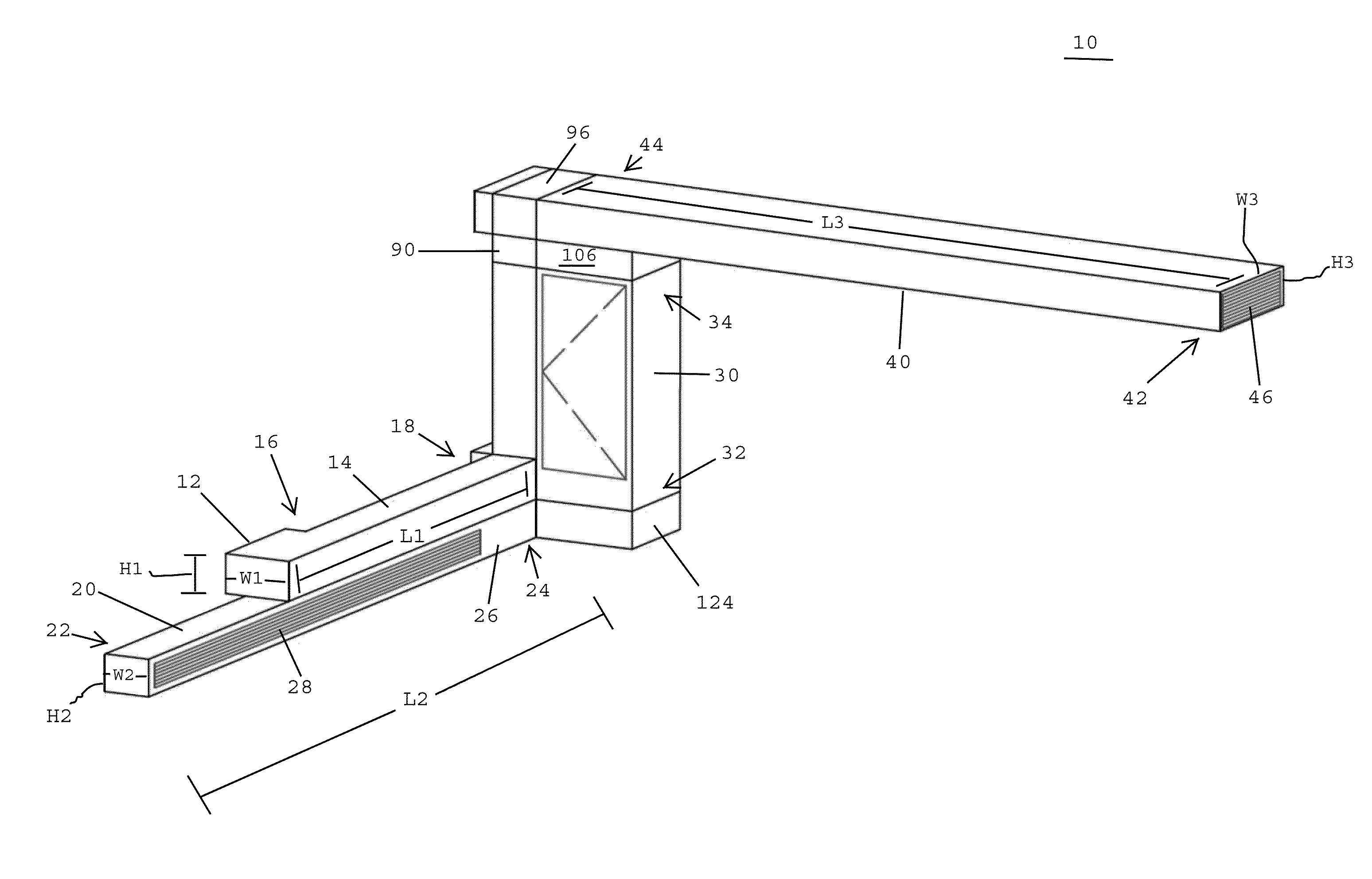
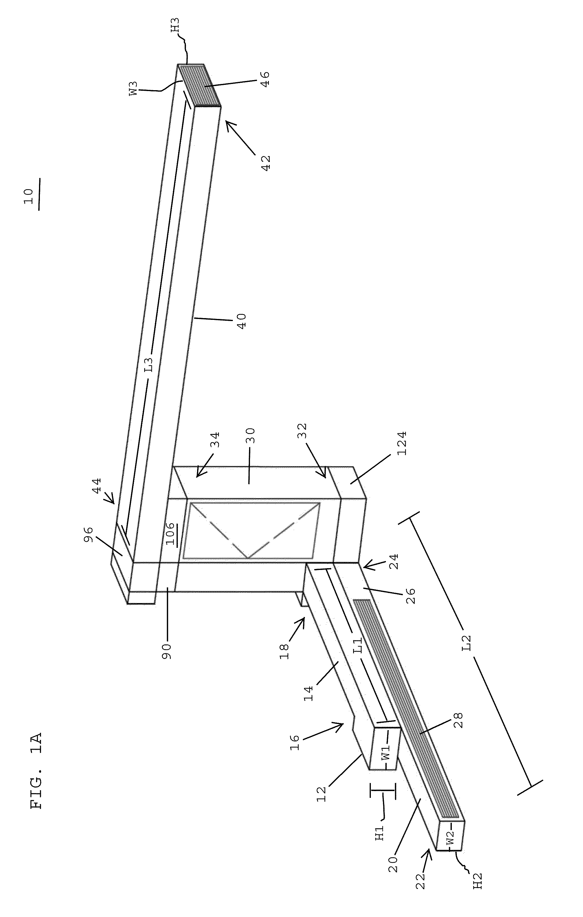
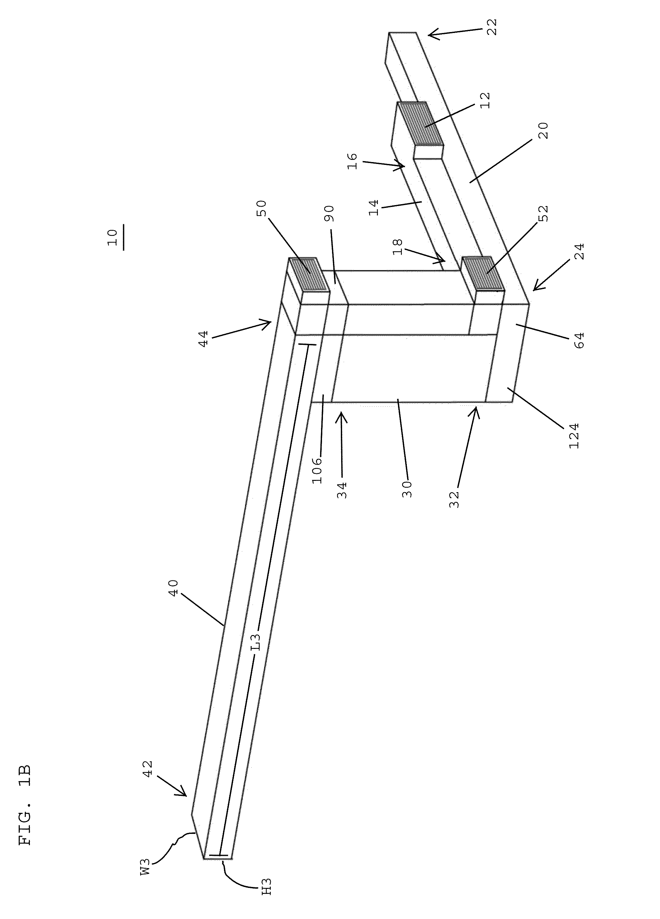
[0040]Referring to FIGS. 1A and 1B, in one embodiment, a displacement ventilation system 10 for ventilating, heating and / or cooling an enclosed space, such as a room within a building, preferably includes an air inlet 12 for supplying outside air to an air inlet duct 14. The air inlet duct 14 preferably has an upstream end 16 adjacent the air inlet 12 and a downstream end 18 remote therefrom. As used herein, the terminology “upstream” and “downstream” indicate the direction of flow of air through the displacement ventilation system of the present application. In one embodiment, the air will flow from the “upstream” region to the “downstream” region. In one embodiment, the air inlet duct 14 preferably extends horizontally over a floor of an enclosed space. In one embodiment, the air inlet duct 14 has a length L1 of between about 12-16 feet, a height H1 of between about 6-18 inches, and a width W1 of between about 18-36 inches. The relatively large dimensions noted above, in compariso...


PUM


Abstract

A displacement ventilation system includes a vertical duct located inside an enclosed space and extending between a floor and a ceiling of the enclosed space, an air inlet coupled with the vertical duct for drawing air into the displacement ventilation system, and an elongated diffuser extending adjacent the floor for diffusing at least some of the outside air over the floor of the enclosed spaced. The displacement ventilation system desirably includes a return air duct extending adjacent the ceiling and being coupled with the vertical duct for removing return air from the enclosed space and advancing the return air toward the vertical duct, a heat exchanger for transferring thermal energy between the return air and the outside air, and a heat pump for changing a temperature level of the outside air or the return air passing through the heat pump.

Description

CROSS REFERENCE TO RELATED APPLICATIONS[0001]The present application claims the benefit of U.S. Provisional Application Ser. No. 61 / 291,770, filed Dec. 31, 2009, the disclosure of which is hereby incorporated by reference herein.BACKGROUND OF THE INVENTION[0002]1. Field of the Invention[0003]The present invention relates to ventilation systems for buildings and more specifically relates to displacement ventilation systems for buildings such as school building, office building, auditoriums, and theatres.[0004]2. Description of the Related Art[0005]Many studies have shown that poor environments in enclosed spaces, which are primarily due to the effects of indoor pollutants, adversely affect the health, attendance, and performance of room occupants. Moreover, it has been determined that there is a direct link between high concentrations of particular air pollutants and reduced attendance levels. Poor environments may also increase microbiological pollutants associated with higher incid...

Claims


Application Information

Patent Timeline
IPC IPC(8): F24F11/00F24F7/00F24F7/007F24F13/10
CPCF24F3/16F24F2011/0006F24F7/06
Inventor CARPENTER, DAVID J.
Owner CARPENTER DAVID J
Why Eureka
Eureka Blog
Learn More