Golf ball mold, golf ball and golf ball manufacturing method

a golf ball and mold technology, applied in the field of golf ball molds, can solve the problems of lack of uniformity in the aerodynamic symmetry of the ball, difficulty in achieving a uniform arrangement of dimples on the spherical surface of the ball, variability in flight performance, etc., to achieve the effect of reducing the diameter of the injection port, reducing the surface area available for providing injection ports, and closer coverage of the surfa

Active Publication Date: 2011-06-30
BRIDGESTONE SPORTS
View PDF10 Cites 3 Cited by
  • Summary
  • Abstract
  • Description
  • Claims
  • Application Information

AI Technical Summary

Benefits of technology

[0007]At the same time, in terms of the aerodynamic properties of a golf ball, it is desirable to provide dimples on a greater portion of the golf ball surface, such advantageous effects being known to increase as the total surface area of the dimples as a proportion of the golf ball surface area (surface area coverage) approaches 100%. Hence, to improve the symmetry of the aerodynamic properties in this way and achieve an even further increase in performance, bringing the dimple surface coverage close to 100% is important.
[0008]In this type of mold, resin injection ports (also referred to below simply as “injection ports”) for introducing resin into the cavity are normally provided along the parting plane. However, circular injection ports having a specific opening surface area in order to keep imbalances in the injection pressure and resin flow rate from arising are generally formed at sizes and positions which do not overlap with the dimple-forming protrusions (on the molded ball surface, at positions which correspond to lands where dimples are not formed). For example, JP-A 2000-42143 mentions providing circular injection ports having a diameter of about 0.5 to about 1.0 mm. However, the intervals between the dimples become smaller as the dimples are arranged more densely so as to bring the dimple surface coverage closer to 100%; as a result, the surface area available for providing injection ports decreases. This problem is commonly addressed by reducing the diameter of the injection ports, but imbalances in the resin injection pressure and flow rate often arise as a result. Hence, when a cover is formed over a core or a sphere composed of a core encased by another layer such as an intermediate layer, the core may end up deformed or the position of the core within the mold may end up off-center, leading to various problems, such as molding defects, scorching or eccentricity. Golf balls with these problems have an inferior quality, such as durability, symmetry and appearance. Also, as shown in FIG. 9, by adjusting the sizes of the dimple-forming protrusions 40 and making the interval between those dimple-forming protrusions 40 which adjoin the injection port 20 larger, it is possible to secure the surface area of the opening in the injection port 20, although further increase in the uniformity of the aerodynamic properties or the surface coverage is difficult.
[0009]Thus, various innovations have hitherto been made to increase the dimple surface coverage and thereby enhance the aerodynamic properties of the ball. However, a fundamental solution to the conflicting problems of mold design and dimple design has yet to be achieved. Accordingly, an approach that resolves the above problems has been sought, both in order to further enhance the aerodynamic properties of the golf ball and also to improve the degree of freedom in mold design.
[0010]Also, in the prior art, because the basic shape of an injection port is circular, it is difficult to efficiently cool the entire gate area for which the injection port serves as the opening; excessive time has thus been required to cool gate areas. Molding defects sometimes arise at the ball surface near the gates, particularly in cases where a resin material of relatively low hardness is molded. That is, after the resin material has been injection-molded, even when an effort is made to cool the entire gate area, cooling of the resin material within the gate near the center axis thereof is inadequate. As a result, after the resin material within the gate has been cooled and solidified, a gate mark ends up remaining on the surface of the finished ball obtained by parting the top and bottom mold halves, removing the molded ball, and subjecting it to gate cutting treatment, trimming and painting. Such gate marks are conspicuous and detract from the appearance of the ball.
[0011]Examples of prior art directed at injection gates having an injection port in a golf ball mold include JP-A 2000-185117, JP-A 2000-185116, JP-A 09-313647 and JP-A 08-034036.SUMMARY OF THE INVENTION
[0012]It is therefore an object of the present invention to provide a golf ball mold which makes it easy to increase the dimple surface coverage, enables an injection port having an opening with a specific surface area to be provided even when the dimples are densely formed, and enables stable molding to be carried out without giving rise to the above-described production problems. Further objects of the invention are to provide a golf ball molded using such a mold and a method of manufacturing golf balls using such a mold.

Problems solved by technology

However, in a golf ball having at the equator a wide great circle with no dimples lying thereacross, it is difficult to achieve a uniform arrangement of dimples on the spherical surface of the ball.
This leads to a lack of uniformity in the aerodynamic symmetry of the ball, giving rise to a variability in the flight performance depending on where the ball is hit.
This problem is commonly addressed by reducing the diameter of the injection ports, but imbalances in the resin injection pressure and flow rate often arise as a result.
Hence, when a cover is formed over a core or a sphere composed of a core encased by another layer such as an intermediate layer, the core may end up deformed or the position of the core within the mold may end up off-center, leading to various problems, such as molding defects, scorching or eccentricity.
Golf balls with these problems have an inferior quality, such as durability, symmetry and appearance.
However, a fundamental solution to the conflicting problems of mold design and dimple design has yet to be achieved.
Also, in the prior art, because the basic shape of an injection port is circular, it is difficult to efficiently cool the entire gate area for which the injection port serves as the opening; excessive time has thus been required to cool gate areas.
Molding defects sometimes arise at the ball surface near the gates, particularly in cases where a resin material of relatively low hardness is molded.
That is, after the resin material has been injection-molded, even when an effort is made to cool the entire gate area, cooling of the resin material within the gate near the center axis thereof is inadequate.
Such gate marks are conspicuous and detract from the appearance of the ball.

Method used


Image

  • Golf ball mold, golf ball and golf ball manufacturing method
  • Golf ball mold, golf ball and golf ball manufacturing method
  • Golf ball mold, golf ball and golf ball manufacturing method

Examples


examples

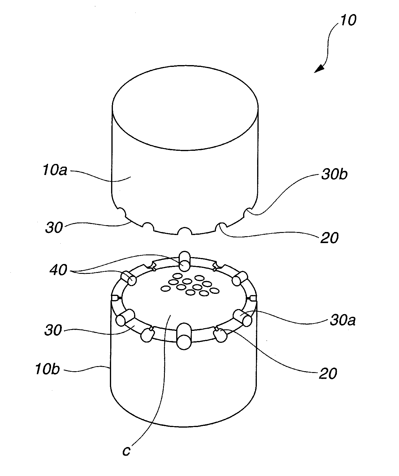
[0063]Using a cis-1,4-polybutadiene-based rubber material, cores having a diameter of 37.3 mm were fabricated for each example. Next, an inner cover layer composed primarily of an ionomeric resin was injection-molded to a thickness of 1.7 mm over the core in each example, thereby giving intermediate spheres in the respective examples. Then, in the respective examples, using the type of injection gate indicated in Table I, and using the respective molds of Examples I to III having six injection gates uniformly disposed along the parting line, a cover material composed primarily of urethane resin was injection-molded to a thickness of 1.0 mm, thereby forming an intermediate sphere in each example. As a result, a molded ball which had inner and outer cover resin layers formed on the core surface, the same arrangement of dimples, and a diameter of 42.70 mm and a weight of 45.30 g was fabricated in each example.

[0064]After injection molding, the cover resin material was water-cooled by m...


PUM

PropertyMeasurementUnit
distanceaaaaaaaaaa
sizeaaaaaaaaaa
surface areaaaaaaaaaaa

Abstract

The invention provides a golf ball mold that is composed of a plurality of mold parts which removably mate to form a cavity having an inner wall with a plurality of dimple-forming protrusions thereon, wherein a non-circular resin injection port for injecting into the cavity a resin material is formed between a plurality of mutually adjoining dimple-forming protrusions which include a plurality of dimple-forming protrusions that lie across a parting line of the mold. Also provided is a golf ball molded using such a mold, and a golf ball manufacturing method which uses such a mold.By using the golf ball mold of the invention, even when manufacturing golf balls with a high dimple surface coverage on which the dimples are tightly arranged, particularly up to the vicinity of the resin injection port, imbalances in the resin injection pressure and flow rate during injection molding are suppressed, enabling golf balls to be manufactured without giving rise to production problems such as molding defects, scorching, or deformation and eccentricity of the core.Moreover, in the mold of the invention, when equally spaced lines are drawn at 0.05 mm intervals from an inner peripheral wall toward a center axis of a gate having the non-circular resin injection port, by adjusting the cross-sectional size of the gate so that the distance between the center of a region enclosed by the innermost equally spaced line and the inner peripheral wall of the gate is less than 0.5 mm, the molten resin material within the gate area can be efficiently and thoroughly cooled after injection molding, thus giving the finished ball a good appearance and enabling productivity to be enhanced.

Description

CROSS-REFERENCE TO RELATED APPLICATION[0001]This application is a continuation-in-part of copending application Ser. No. 12 / 648,513 filed on Dec. 29, 2009, the entire contents of which are hereby incorporated by reference.BACKGROUND OF THE INVENTION[0002]The present invention relates to a golf ball mold suitable for molding solid golf balls composed of a core encased by one or more cover layer, and thread-wound golf balls. The invention relates also to golf balls molded using such a mold, and to a method of manufacturing golf balls using such a mold.[0003]Molds for molding golf balls are generally composed of a plurality of parts which removably mate to each other; a golf ball is manufactured by feeding a golf ball molding material to a cavity that forms at the interior of the mold when these mold parts are mated. From the standpoint of ease of mold fabrication and ball moldability, etc., the parting plane of the mold parts is often rectilinear in shape without concavities and conve...

Claims


Application Information

Patent Timeline
Patent Type & Authority Applications(United States)
IPC IPC(8): A63B37/14B29C45/14B29C37/00
CPCA63B37/0003A63B37/14A63B45/00B29C45/2708B29C45/372B29L2031/54A63B37/0083A63B37/002A63B37/0021A63B37/0031A63B37/0033A63B37/0075A63B37/008A63B37/0019
Inventor NAKAGAWA, TAKUMASATO, KATSUNORI
Owner BRIDGESTONE SPORTS
Why Eureka
Try Eureka