Medical port

a technology for medical devices and ports, applied in the field of medical devices, can solve the problems of contamination of needles, liquid leakage from that position, etc., and achieve the effect of suppressing the occurrence of liquid leakag

Active Publication Date: 2011-06-30
JMS CO LTD
View PDF25 Cites 24 Cited by
  • Summary
  • Abstract
  • Description
  • Claims
  • Application Information

AI Technical Summary

Benefits of technology

[0014]In the medical port of the present invention, the annular protrusion is formed in the valve so that in the state in which the inserting body is locked against the cover, the annular protrusion is in contact with the outer circumferential surface of the leading end portion of the inserting body. Thus, the tightness of contact between the outer circumferential surface of the leading end portion of the inserting body and the valve is improved, and so the occurrence of liquid leakage is suppressed.

Problems solved by technology

However, there has been a problem in that if a region of the plug other than a predetermined region to be pierced is pierced with the needle, liquid leakage from that position may occur.
In addition, there has been a problem of contamination of the needle due to, for example, a mistake in operation.

Method used


Image

  • Medical port
  • Medical port
  • Medical port

Examples


embodiment 1

[0052]Next, an example of a medical port according to Embodiment 1 of the present invention will be described using FIGS. 1 to 12.

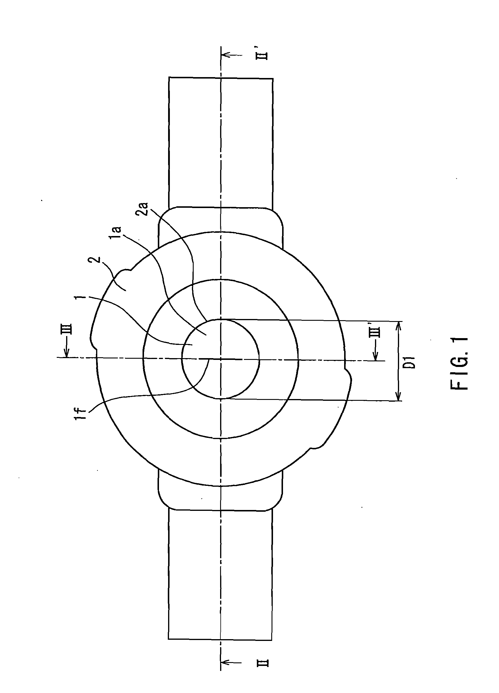
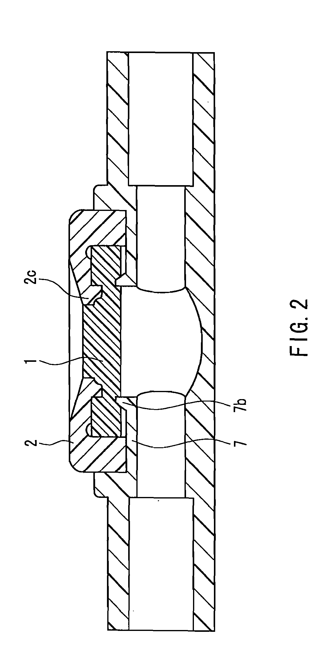
[0053]As shown in FIGS. 1 to 3, the example of the medical port of the present invention includes a disc-shaped valve 1, a base seat 7 that supports a peripheral edge of the valve from a lower surface side of the valve, and a cover 2.

[0054]As shown in FIG. 1, the cover 2 has, for example, an approximately circular shape when viewed from above. The cover 2 has a fitting hole 2a through which an upper surface of a central portion 1a of the valve 1 can be exposed. As shown in FIG. 4, the cover 2 has, for example, at least two notches 2b in lateral portions thereof the notches 2b are engaged with projections 7a (see FIG. 3) of the base seat 7, and thus the valve 1 is held by the base seat 7 and the cover 2. Assuming that a luer at the tip of a common syringe or a luer of a male connector constituting an infusion or a transfusion set is used as the inserting b...

embodiment 2

[0072]Next, an example of a medical port according to Embodiment 2 of the present invention will be described using FIGS. 13 to 21. FIG. 13 is a plan view of the example of the medical port according to the present embodiment, FIG. 14 is a cross-sectional view of the medical port of the present invention shown in FIG. 13 taken along line XIV-XIV′, and FIG. 15 is a cross-sectional view of the medical port of the present invention shown in FIG. 13 taken along line XV-XV′.

[0073]In the lower surface of the valve 1 of the medical port of the present embodiment, protrusions are formed in respective positions that are on a straight line extending in the same direction as the longitudinal direction of the insertion hole 1f and in the vicinity of both ends of the insertion hole 1f in the longitudinal direction. Each protrusion, for example, defines part of a ring-shaped protrusion 1e that is formed so as to surround the insertion hole 1f. The medical port of the present embodiment otherwise ...

example 1

[0083]Medical ports having the form shown in FIGS. 1 to 3 were made. In these medical ports, the diameter D2 (see FIG. 7) of the valve is 10 mm, the length L0U of the insertion hole (the slit) in the upper surface of the valve in the longitudinal direction is 3.1 mm, the length L0d of the insertion hole 1f in the lower surface of the valve 1 in the longitudinal direction is 2.9 mm, the diameter D1 (see FIG. 1) of the fitting hole is 4.2 mm, the outer diameter W1 (see FIG. 7) of the central portion as seen when the valve 1 is viewed from above from its upper surface side is 4.1 mm, the outer diameter W2 (see FIG. 7) of the annular protrusion as seen when the valve 1 is viewed from above from its upper surface side is 5.1 mm, the radius of curvature of the radiused surface of the annular protrusion is 0.1 mm, the thickness of the thinnest part of the annular groove 1c is 0.9 mm, the thickness L1 (see FIG. 8) of the portion 1b of the valve 1 outside the annular groove 1c is 1.5 mm, and...


PUM


Abstract

A medical port includes a disc-shaped valve 1 in which an insertion hole is formed in a central portion 1a, a base seat 7 that supports the valve from a lower surface side, and a cover 2 that has a fitting hole exposing an upper surface of the central portion of the valve and covers at least a peripheral edge of the valve from the upper surface side, the fitting hole being formed so that when an inserting body has been inserted into the insertion hole, a fit between the inserting body and the fitting hole can cause the inserting body to be locked against the cover. An annular protrusion 1d is formed in the valve 1, the annular protrusion being continuous in the circumferential direction, and formed in the valve 1 so that in the state in which the inserting body is locked against the cover, the annular protrusion is in contact with an outer circumferential surface of a leading end portion of the inserting body.

Description

TECHNICAL FIELD[0001]The present invention relates to a medical port through which a liquid such as a drug solution can be injected and / or collected.BACKGROUND ART[0002]When a drug solution or the like is administered to a patient, a drug solution that is different from the principal drug solution may be coinjected into a liquid feed passage for drug solution supply, or a liquid flowing through the above-described liquid feed passage may be sampled. In such cases, conventionally, a plug made of rubber is provided in the liquid feed passage as a coinjection port, and the plug is pierced with an injection needle or the like to coinject the drug solution or to collect the liquid.[0003]However, there has been a problem in that if a region of the plug other than a predetermined region to be pierced is pierced with the needle, liquid leakage from that position may occur. In addition, there has been a problem of contamination of the needle due to, for example, a mistake in operation. Recen...

Claims


Application Information

Patent Timeline
Patent Type & Authority Applications(United States)
IPC IPC(8): A61M5/00
CPCA61M39/045A61M2039/0072A61M2039/0036A61M39/26A61J1/14A61M39/02A61M39/22A61M39/04
Inventor OKIYAMA, TADASHITACHIZAKI, HITOSHI
Owner JMS CO LTD
Why Eureka
Try Eureka