Electromagnetic actuator

a solenoid and electromagnetic actuator technology, applied in the direction of magnets, operating means/releasing devices of valves, magnetic bodies, etc., can solve the problems of poor molding, inability to make the flow of molding resin uniform in the whole periphery, and the miniaturization of electromagnetic actuators, so as to prevent the amount of magnetic flux passing through the stator flange from decreasing, and ensure the effect of magnetic flux amoun

Active Publication Date: 2009-01-06
DENSO CORP
View PDF5 Cites 13 Cited by
  • Summary
  • Abstract
  • Description
  • Claims
  • Application Information

AI Technical Summary

Benefits of technology

[0009]The present invention has been achieved in view of the problems and an object of the invention is to provide an electromagnetic actuator in which an amount of magnetic flux passing through a stator flange is prevented from decreasing and occurrence of poor molding is suppressed.
[0011]With the arrangement, a molding resin flows through the resin-passing gap at the time of molding. That is, the resin-passing gap in the positioning hole plays the role of a resin-passing hole. Consequently, the total number of the positioning holes and the resin passing holes formed in the stator flange can be made smaller than that in the conventional art, and the amount of magnetic flux passing through the stator flange can be prevented from decreasing. Since the amount of magnetic flux passing through the stator flange can be prevented from decreasing, even when the diameter of the stator flange is made smaller, the magnetic flux amount can be assured, and the electromagnetic actuator can be miniaturized.
[0012]Moreover, a molding resin flows through the resin-passing gap in the portion of the positioning means (the fitting portion between the positioning hole and the positioning projection) of the bobbin and the stator, so that the flow of the molding resin can be made uniform in the whole periphery. Occurrence of poor molding can be prevented, and a very reliable electromagnetic actuator can be provided.

Problems solved by technology

In particular, when the electromagnetic actuator is miniaturized, the sectional area of a magnetic circuit becomes insufficient due to the many resin-passing holes, and it disturbs miniaturization of the electromagnetic actuator.
In the conventional art, however, the molding resin does not flow smoothly in the positioning means (the fitting portion between the positioning holes and the positioning projections) of the bobbin and the stator, so that the flow of the molding resin cannot be made uniform in the whole periphery, and poor molding tends to occur.

Method used


Image

  • Electromagnetic actuator
  • Electromagnetic actuator
  • Electromagnetic actuator

Examples


first embodiment

[0022]A first embodiment in which an electromagnetic actuator of the present invention is applied to an oil flow control valve (hereinbelow, OCV) in a valve variable timing apparatus (hereinbelow, VVT) will be described with reference to the drawings.

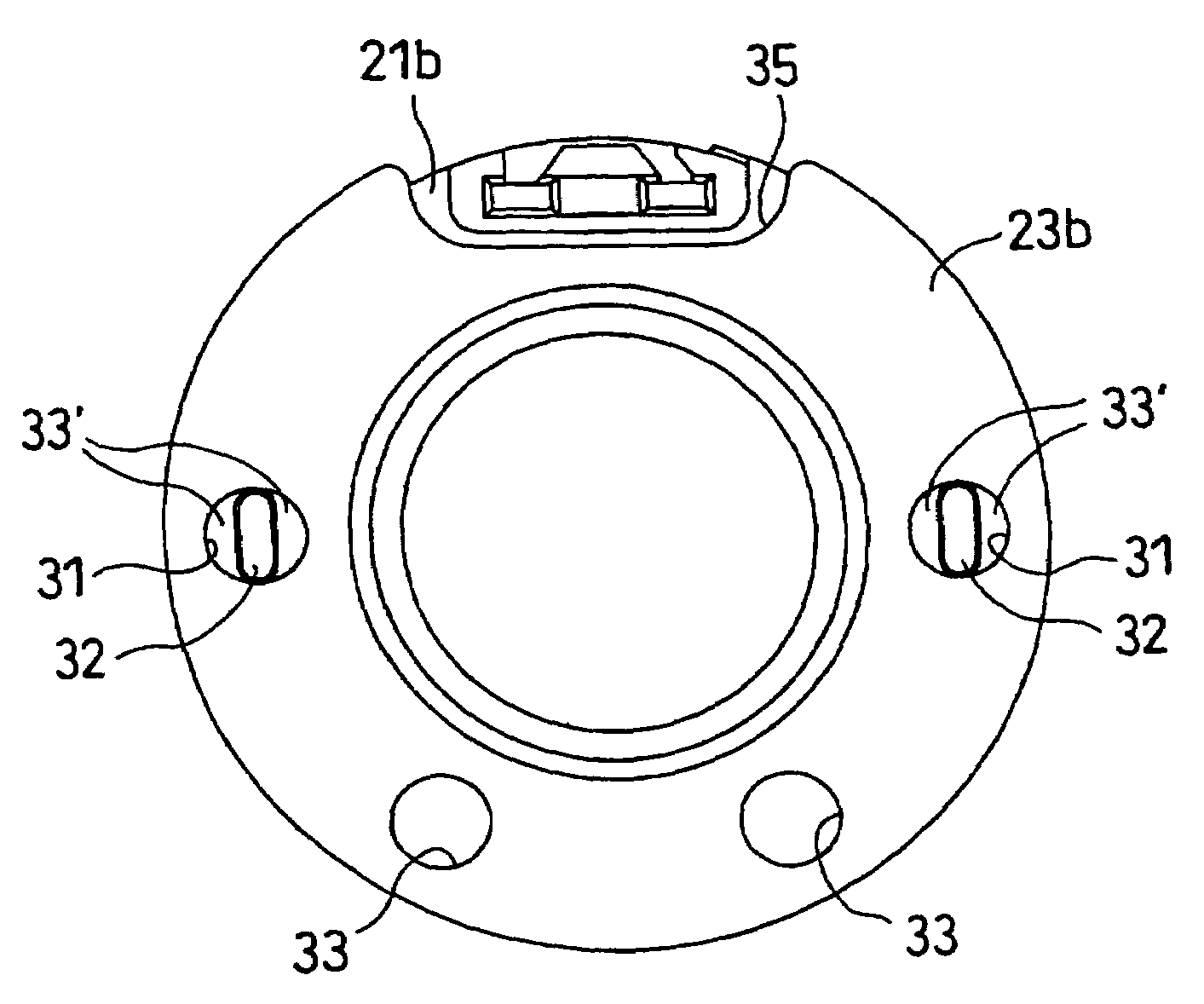
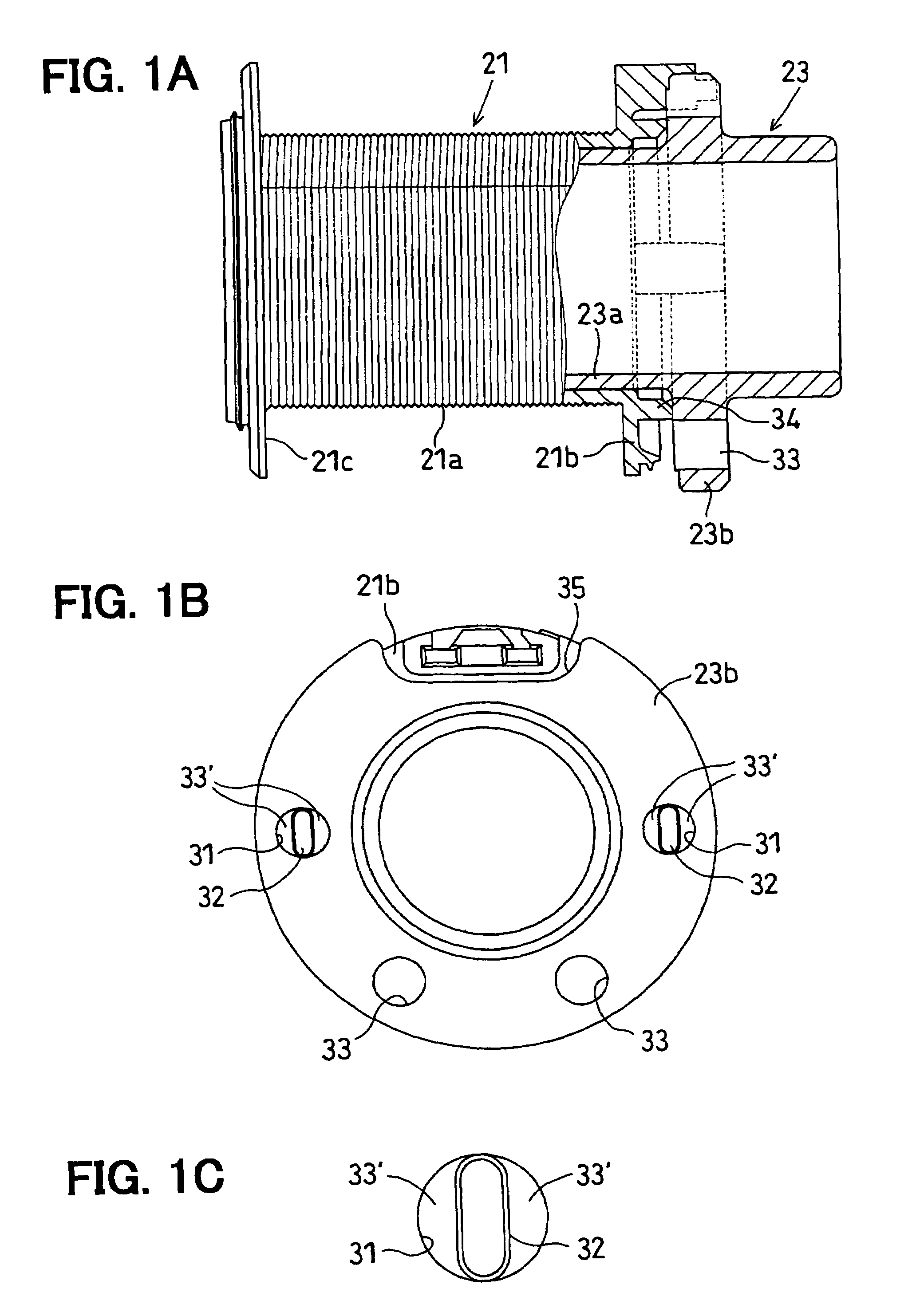
[0023]In the first embodiment, the structure of the VVT will be described first with reference to FIG. 4. Next, the structure of the OCV will be described with reference to FIG. 3. After that, the feature part to which the invention is applied will be described with reference to FIGS. 1A to 1C and FIG. 2.

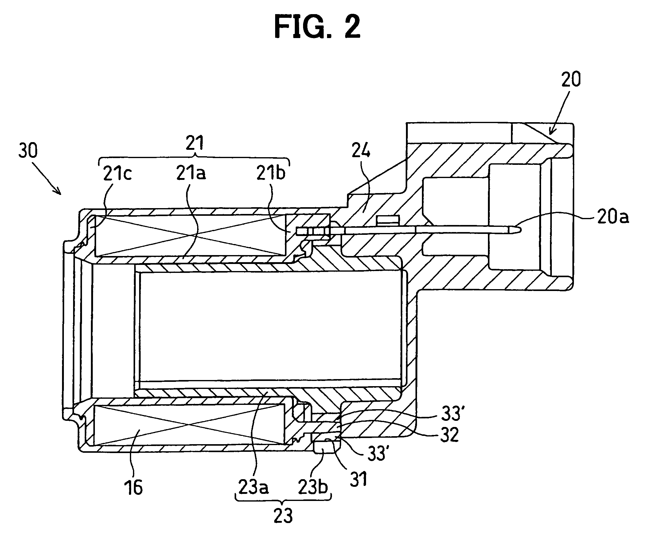
[0024]The VVT includes a valve timing varying mechanism (hereinbelow, VCT) 1 attached to a camshaft (for an intake valve, exhaust valve, or intake / exhaust valve) of an internal combustion engine (hereinbelow, called an engine) and capable of continuously varying timings of opening / closing a valve, a hydraulic circuit 2 for hydraulic-controlling the operation of the VCT 1, and an ECU (Engine Control Unit) 4 for electrically controlling a...

second embodiment

[0084]A second embodiment will be described with reference to FIGS. 5A to 5C. In the following, the same reference numerals denote the same function members as those of the first embodiment.

[0085]In the first embodiment, the example of forming the positioning hole 31 in a circular shape has been described.

[0086]In contrast, in the second embodiment, the positioning hole 31 is formed in a rectangular shape.

[0087]Concretely, the positioning hole 31 of the second embodiment has a rectangular shape penetrating in the axial direction as shown in FIGS. 5B and 5C. In a manner similar to the first embodiment, two positioning holes 31 are provided in facing positions in the stator flange 23b.

[0088]The positioning projection 32 of the second embodiment has a flat shape which matches a center portion of the rectangular hole in the circumferential direction. The shape seen in the axial direction of the positioning projection 32 is a flat oval shape which is flatter than the positioning hole 31...


PUM


Abstract

A bobbin and a magnetic transmitting / receiving stator are positioned by fitting two positioning projections provided for a bobbin flange into two positioning holes formed in a stator flange. The positioning hole has a circular shape and the positioning projection has a flat oval shape which matches a diameter part of the circular shape so that a resin-passing gap is formed between the shapes. Since the resin-passing gap plays the role equivalent to the role of a resin passing hole, the total number of positioning holes and the resin passing holes can be reduced, and magnetic flux passing through the stator flange can be prevented from decreasing. Since a post-forming resin flows through the resin-passing gap in the positioning part, the flow of the post-forming resin can be made uniform in the whole periphery, and occurrence of poor molding can be restricted.

Description

CROSS-REFERENCE TO RELATED APPLICATION[0001]This application is based on Japanese Patent Application No. 2006-2697 filed on Jan. 10, 2006, the disclosure of which is incorporated herein by reference.FIELD OF THE INVENTION[0002]The present invention relates to a solenoid in an electromagnetic actuator and, more particularly, to a resin mold made of a bobbin around which a coil is wound and a stator.BACKGROUND OF THE INVENTION[0003]An electromagnetic actuator obtained by molding a bobbin around which a coil is wound and a stator with a molding resin is known (for example, U.S. Pat. No. 6,688,334B2).[0004]The bobbin and the stator are assembled at the time of molding a bobbin and a stator. The bobbin and the stator are positioned by fitting a positioning projection provided on a bobbin flange to a positioning hole formed in a stator flange as positioning means.[0005]In the stator flange, a resin-passing hole for passing a molding resin has to be formed. A plurality of resin passing hol...

Claims


Application Information

Patent Timeline
Patent Type & Authority Patents(United States)
IPC IPC(8): F16K31/02
CPCF16K31/061Y10T137/86622
Inventor MURAO, YOSHIYUKIKONDO, JIRO
Owner DENSO CORP
Why Eureka
Try Eureka