Magnetic toner and method of manufacturing magnetic toner

a technology of magnetic toner and manufacturing method, which is applied in the field of magnetic toner, can solve the problems of reduced flowability, environmental stability, and reduced frictional chargeability of toner, and achieves the suppression of fogging, stable charging performance, and high image density

Inactive Publication Date: 2008-05-13
CANON KK
View PDF26 Cites 13 Cited by
  • Summary
  • Abstract
  • Description
  • Claims
  • Application Information

AI Technical Summary

Benefits of technology

[0015]An object of the present invention is to provide a magnetic toner that has solved the above problems. That is, an object of the present invention is to provide a magnetic toner which is hardly influenced by an environment, which has stable charging performance, which provides a high image density even in long-term use, in which the occurrence of fogging is suppressed, and which is excellent in image reproducibility.
[0016]Another object of the present invention is to provide a magnetic toner with which an image can be stably formed even under a low-temperature and low-humidity environment, and which has few image defects such as fogging resulting from the deterioration of chargeability of toner at the time of durable use.
[0017]Still another object of the present invention is to provide a magnetic toner which provides a sufficient image density particularly in a fine isolated dot, which provides high image quality, and the consumption of which is low, and to provide a method of manufacturing the toner.
[0018]The inventors of the present invention have made extensive studies on the uniformization and stabilization of chargeability of a magnetic toner particularly under a low-temperature and low-humidity environment. As a result, the inventors have found that the following toner is excellent in image property such as developability or transferability, has improved durability, and, in particular, has a high coloring power, so that the toner consumption can be reduced. In the toner, no magnetic iron oxide fine particles are exposed to the toner particle surface and magnetic iron oxide fine particles are concentrated in the vicinity of the toner particle surface. Thus, the toner of the present invention has been completed.

Problems solved by technology

However, a development method using magnetic toner inevitably poses a problem owing to the magnetic toner to be used.
The problem is such that the flowability, environmental stability, and frictional chargeability of the toner reduce because a considerable amount of magnetic material in fine powder form is mixed and dispersed in the toner and part of the magnetic material is exposed to the toner particle surface.
Thus, the toner deteriorates, with the result that image failures such as a reduction in image density and uneven in density called sleeve ghost occur.
However, it has been recently found out that a toner of such a form poses several problems in achieving an increase in image quality when the toner has a small average particle diameter, for example, an average particle diameter of 10 μm or less.
One of the problems is that charge up easily occurs under a low-temperature and low-humidity environment.
However, neither of those prior arts has made an investigation into embedding of an external additive into toner particles, so that the durability is susceptible to improvement.
A ratio of power consumption at the fixation step to the total power consumption is considerably large, so that the power consumption increases with increasing fixation temperature.
Furthermore, a problem such as curling of printed-out paper occurs with increasing fixation temperature.
However, the compatibility between the low-temperature fixability and offset resistance of the toner is still susceptible to improvement even when such a magnetic material is used, specially an improvement in fixability has been insufficient.
In particular, when a process speed is high, a time period during which the toner and a fixing unit are in contact with each other at the time of fixation is extremely short, so that the toner receives a limited heat quantity.

Method used


Image

  • Magnetic toner and method of manufacturing magnetic toner
  • Magnetic toner and method of manufacturing magnetic toner
  • Magnetic toner and method of manufacturing magnetic toner

Examples


example 1

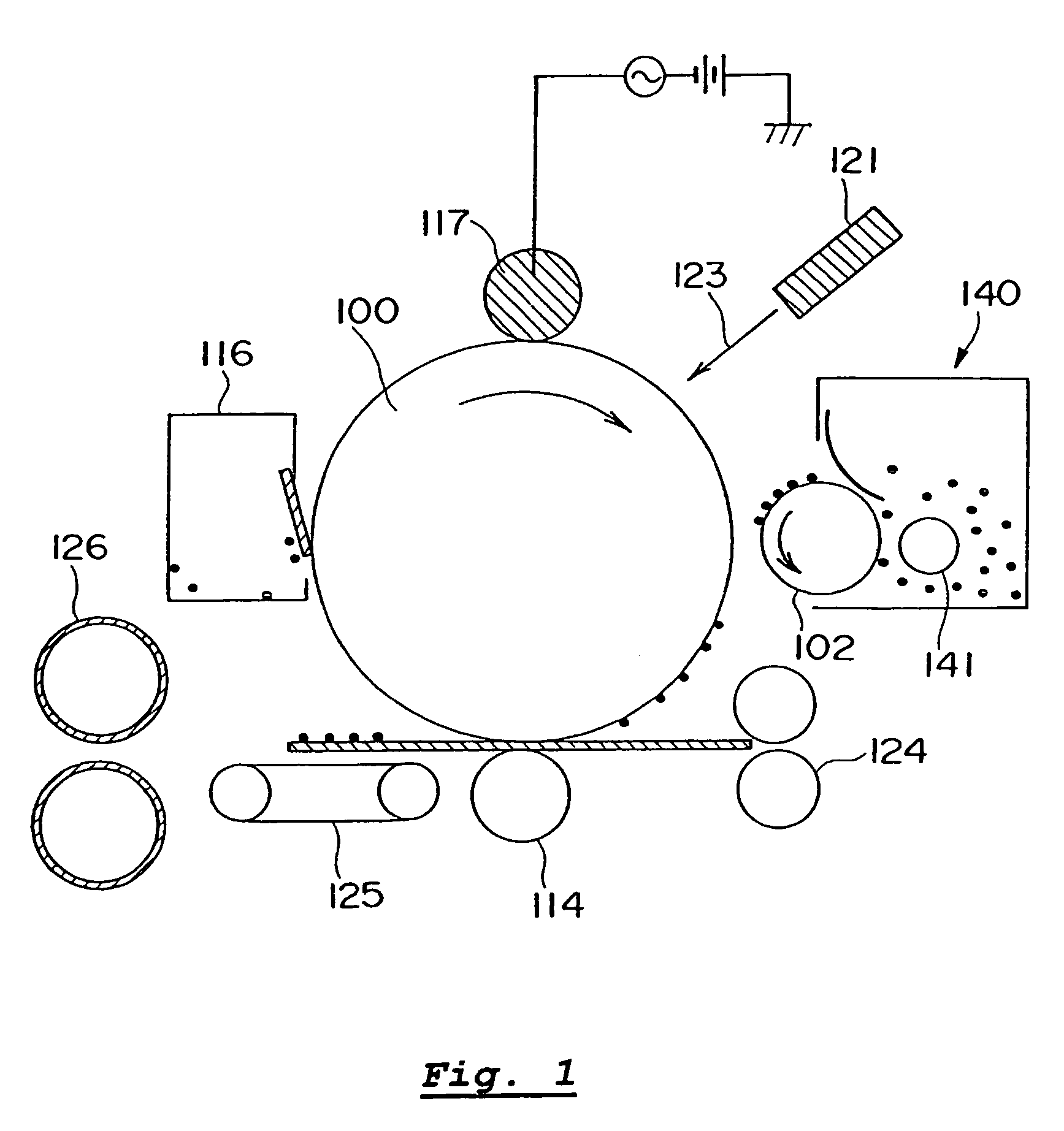
[0222]Used as an image forming apparatus was a remodeled apparatus of LBP-1760 (manufactured by Canon Inc.) and having such a configuration as one shown in FIG. 1.

[0223]An electrostatic image bearing member (photosensitive drum) of the apparatus had a dark-part potential Vd of −700 V and a light-part potential VL Of −150 V. A gap between the electrostatic image bearing member and a developing sleeve was 290 μm. Used as a toner bearing member was a developing sleeve having a resin layer with a thickness of about 7 μm (JIS central line average roughness (Ra)=1.0 μm; a layer formed by dispersing 90 parts of graphite (particle diameter about 7 μm) and 10 parts of carbon black into 100 parts of phenol resin) formed on a surface-blasted aluminum cylinder having a diameter of 16 mm. A urethane blade having a thickness of 1.0 mm and a free length of 0.5 mm was used as a toner regulating member, and was brought into contact with the developing sleeve under a linear pressure of 29.4 N / m (30 g...

examples 2 to 10

[0250]In each example, an image output test was performed under conditions identical to those of Example 1 by using any one of the magnetic toners B to J. As a result, initial image properties presented no problems, and each example provided a result without a serious problem until the printing of 10,000 sheets. Table 3 shows the evaluation results under a normal-temperature and normal-humidity environment while Table 4 shows the evaluation results under a low-temperature and low-humidity environment.

example 11

[0279]Used as an image forming apparatus was a remodeled apparatus of LBP-1760 and having such a configuration as one shown in FIG. 1.

[0280]An electrostatic image bearing member (photosensitive drum) of the apparatus had a dark-part potential Vd of −650 V and a light-part potential VL of −130 V. A gap between the electrostatic image bearing member and a developing sleeve was 270 μm. Used as a toner bearing member was a developing sleeve having a resin layer with a thickness of about 7 μm (JIS central line average roughness (Ra)=1.0 μm; a layer formed by dispersing 90 parts of graphite (particle diameter about 7 μm) and 10 parts of carbon black into 100 parts of phenol resin) formed on a surface-blasted aluminum cylinder having a diameter of 16 mm. A urethane blade having a thickness of 1.0 mm and a free length of 0.5 mm was used as a toner regulating member, and was brought into contact with the developing sleeve under a linear pressure of 39.2 N / m (40 g / cm). In addition, a magnet r...


PUM


Abstract

The present invention provides a magnetic toner which is hardly influenced by an environment, and with which an image with high quality and excellent resolution can be stably even under low humidity. In the magnetic toner of present invention:I) a ratio of an iron element content to a carbon element content present on the toner particle surface is less than 0.0010;II) 50 number % or more of toner particles satisfy a relationship of D / C≦0.02 (C: projected area diameter of toner particles, D: minimum value for a distance between a magnetic iron oxide fine particle and the toner particle surface); andIII) 40-95 number % of toner particles satisfy a structure where 70 number % or more of the magnetic iron oxide fine particles in the respective toner particles are present up to a depth of 0.2 time as far as C from the toner particle surface.

Description

BACKGROUND OF THE INVENTION[0001]1. Field of the Invention[0002]The present invention relates to a magnetic toner used for developing an electrostatic image which is formed according to an image forming method such as an electrophotographic method, an electrostatic recording method, a magnetic recording method, or a toner jet recording method.[0003]2. Description of the Related Art[0004]A large number of methods have been conventionally known as electrophotographic methods. A general electrophotographic method involves: forming an electrostatic latent image on an electrostatic image bearing member (hereinafter, referred to as “photosensitive member”) using a photoconductive substance with various means; developing the latent image with toner to obtain a visible image (toner image); transferring the toner image onto a recording medium such as paper as required; and fixing the toner image onto the recording medium by means of heat, pressure, or the like to obtain a copied product.[000...

Claims


Application Information

Patent Timeline
Patent Type & Authority Patents(United States)
IPC IPC(8): G03G9/083G03G9/08G03G9/087
CPCG03G9/08G03G9/083G03G9/087G03G9/0806G03G9/0833G03G9/0834G03G9/08791
Inventor CHIBA, TATSUHIKOMAGOME, MICHIHISAYANASE, ERIKOKABURAGI, TAKESHI
Owner CANON KK
Why Eureka
Try Eureka