Control device for robot

a control device and robot technology, applied in the field of robot control devices, can solve the problems of inconvenient presentation of poor flexibility in response to a change in an external force acting on the robot, difficult to maintain a stable posture of the robot, and significant restrictions on the actual motion of each joint of the entire robot, so as to enhance the flexibility of the motion of the joints

Active Publication Date: 2011-06-30
HONDA MOTOR CO LTD
View PDF8 Cites 67 Cited by
  • Summary
  • Abstract
  • Description
  • Claims
  • Application Information

AI Technical Summary

Benefits of technology

[0010]The present invention has been made with the background described above, and it is an object of the invention to provide a control device capable of controlling a driving force to be imparted to each joint of a robot to a driving force that is proper for causing the robot to perform a desired motion while enhancing the flexibility of the motion of joints of the robot in the case where the motion of the robot is controlled by force control.

Problems solved by technology

According to the position control described above, the actual displacement amount of a joint is maintained to be constant as long as the desired displacement amount of the joint remains constant, thus inconveniently presenting poor flexibility in response to a change in an external force acting on the robot.
Thus, according to the technique disclosed in Japanese Patent Application Laid-Open No. 2007-160446, the actual motion of each joint of the entire robot will be significantly susceptible to restrictions based on the desired values of the rotational angle, the angular velocity and the angular acceleration of each joint.
Therefore, according to the technique disclosed in Japanese Patent Application Laid-Open No. 2007-160446, the actual motion of each joint of the robot will be undesirably least flexible, possibly making it difficult to maintain a stable posture of the robot when, for example, an external force acting on the robot suddenly changes.

Method used


Image

  • Control device for robot
  • Control device for robot
  • Control device for robot

Examples


first embodiment

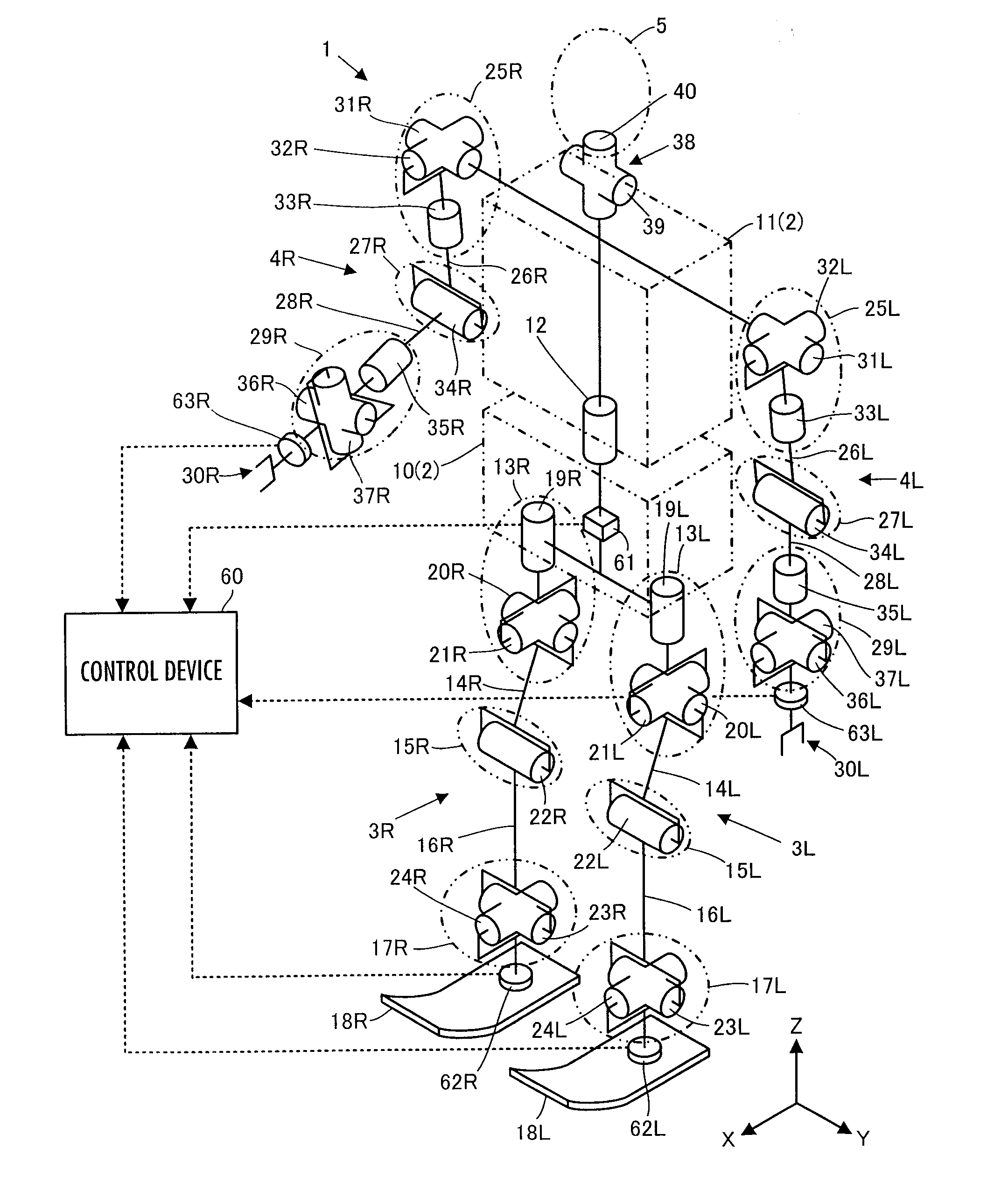
[0082]The following will describe a first embodiment of the present invention with reference to FIG. 1 to FIG. 5.

[0083]FIG. 1 schematically illustrates the skeleton framework of a robot illustrated in the present embodiment. This robot 1 is a bipedal mobile robot as a legged mobile robot. The robot 1 is roughly constituted of a body link 2, a pair of right and left leg links 3R, 3L, a pair of right and left arm links 4R, 4L, and a head 5.

[0084]In the present description, a member on the right side observed facing to the front of the robot 1 or a variable indicating a quantity associated with the member will be suffixed by a character “R,” while a member on the left side observed facing to the front of the robot 1 or a variable indicating a quantity associated with the member will be suffixed by a character “L.” However, the characters “R” and “L” may be omitted unless it is particularly necessary to distinguish between the right side and the left side.

[0085]The body link 2 is consti...

second embodiment

[0315]A second embodiment of the present invention will now be described with reference mainly to FIG. 6.

[0316]The present embodiment differs from the first embodiment in the method for setting a contact portion representative element in the processing by a desired joint driving torque determiner 72 of a control device 60. Accordingly, in the processing by a desired joint driving torque determiner 72, the processing by a contact portion Jacobian matrix determiner 82, a control input determiner 85, and a compliance controller 86 is partly different from that of the first embodiment. The rest of the processing by the desired joint driving torque determiner 72 (the processing by a basic parameter group determiner 81, a state amount Jacobian matrix determiner 83, and a state amount desired value determiner 84), and the processing by a gait generator 71 and a joint drive controller 73 is the same as that in the first embodiment.

[0317]Therefore, the description of the present embodiment w...


PUM


Abstract

A control device for a robot determines, as a desired driving force to be imparted to a joint, a component value corresponding to the displacement amount of each joint out of a desired generalized force vector τcmd that satisfies the relationship indicated by expression 01 given below by using basic parameter group of M, N, and Jacobian matrixes Jc and Js, a desired value ↑C of the motion acceleration of a contact portion representative element representing a motion of a contact portion of a robot 1, generalized variable observation information, and a desired value ↑S′ of a first-order differential value of a predetermine type of state amount, and then controls the operation of an actuator of the robot 1 on the basis of the determined desired driving force.S′+(Js*M−1*Tc−Js′)*q′=(Js*M−1*Pc)*(τcmd−τcmpn)   Expression 01

Description

BACKGROUND OF THE INVENTION[0001]1. Field of the Invention[0002]The present invention relates to a control device for a robot, such as a legged mobile robot.[0003]2. Description of the Related Art[0004]As a technique for controlling a legged mobile robot, such as a bipedal walking robot, there has been generally known so-called position control proposed in, for example, Japanese Patent Application Laid-Open No. 5-305579 by the applicant of the present application. According to the disclosed technique, the desired displacement amount of each joint of a robot is sequentially determined on the basis of a desired motion of the robot (e.g., the trajectory of a desired position of the distal end of a leg of the robot), and then the actuator of each joint is drivably controlled so as to cause an actual displacement amount to coincide with the desired displacement amount.[0005]According to the position control described above, the actual displacement amount of a joint is maintained to be co...

Claims


Application Information

Patent Timeline
Patent Type & Authority Applications(United States)
IPC IPC(8): G05B15/00
CPCB62D57/032B25J9/1607
Inventor ORITA, ATSUO
Owner HONDA MOTOR CO LTD
Why Eureka
Try Eureka