Method and system for driving light emitting elements

a technology of light emitting elements and drive solutions, applied in the direction of electric variable regulation, process and machine control, instruments, etc., can solve the problems of inability to drive solutions suitable for driving higher power arrays of leds, and high initial cost of state of the art led devices, etc., to achieve accurate current control and low cost

Inactive Publication Date: 2011-07-07
COOLEDGE LIGHTING
View PDF23 Cites 53 Cited by
  • Summary
  • Abstract
  • Description
  • Claims
  • Application Information

AI Technical Summary

Benefits of technology

[0007]The subject matter of the present invention provides a drive circuit and system topology for inexpensive but accurate current control of an array of light emitting elements. It includes a driving circuit having controlled current sources that provide currents for driving strings of series connect...

Problems solved by technology

Many LED light sources employ high powered LEDs, which pose thermal management problems and other related problems.
Another drawback with state of the art LED devices is a high initial cost.
These drive solutions are not appropriate for driving higher power arrays of LEDs, for example an array of hundreds or even thousands of low power micro-LEDs with a total LED power exceeding for example 10 watts.
Even employing the lowest cost “multi-LED” linear regulator drive circuits currently on the market, with up to eight outputs each of up to 20 mA at ˜24 VDC, would require hundreds of...

Method used


Image

  • Method and system for driving light emitting elements
  • Method and system for driving light emitting elements
  • Method and system for driving light emitting elements

Examples


first embodiment

[0045

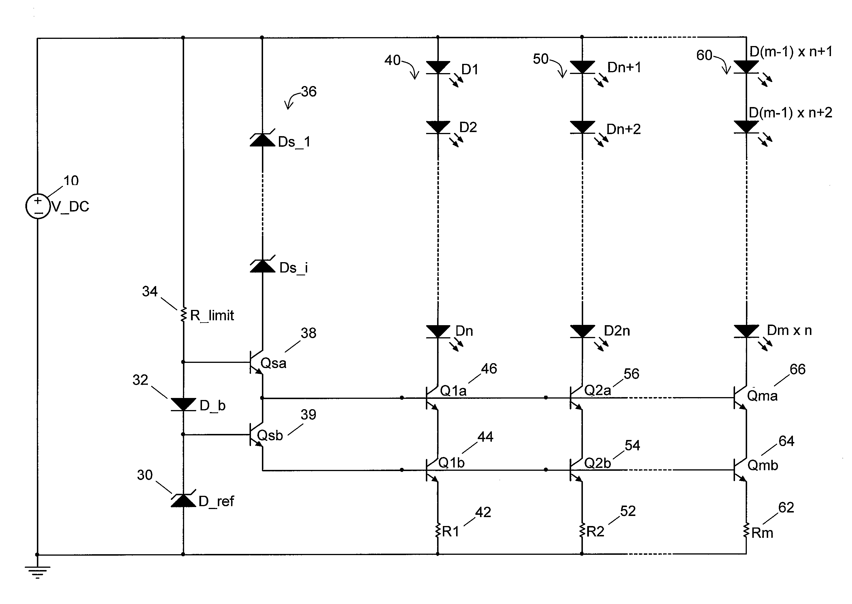
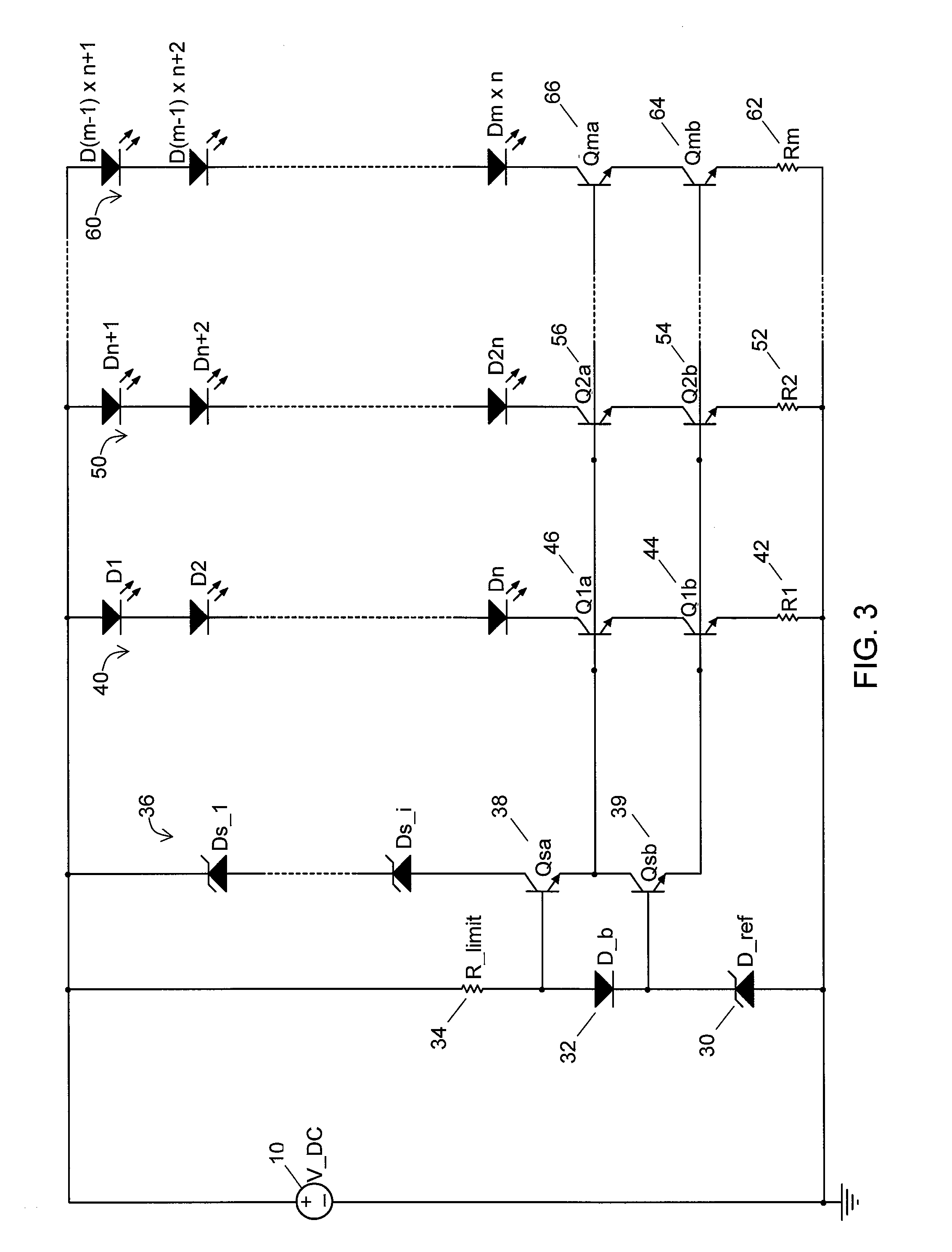
[0046]Referring again to FIG. 3, in a first exemplary embodiment of a light emitting element drive circuit of the present invention the voltage source V_DC 10 is a DC voltage supply. The zener diode D_ref 30 with zener voltage V(D_ref) establishes the reference voltage and hence the drive current for each LED string 40, 50, 60. The LED drive current in a given string is set to the desired level by current setting resistors R1 through Rm (42, 52, 62) according to the following relation:

I_LED=(V(D_ref)−2Vbe) / R

[0047]where R is the resistance of a given current setting resistor R1 through Rm 42, 52, 62 and Vbe is the base emitter voltage drop of transistor Qsb 39 and transistor Q1b 44, Q2b 54, Qmb 64 in each current source. If the values of resistors R1 through Rm 42, 52, 62 are equal, then the LED current through each string 40, 50, 60 will be essentially equal. To minimize the power loss in the current setting resistors 42, 52, 62, zener diode D_ref 30 should preferably be selec...

second embodiment

[0053]Digital Control

[0054]Referring now to FIG. 4, in a second exemplary embodiment of the light emitting element drive circuit of the present invention the current through all the LED strings 40, 50, 60 is controlled with a single digital control input 72. Transistor Qdim 70 is placed in parallel with zener diode D_ref 30, with a pull-down resistor 74 on its base where the digital control input 72 can be connected. As noted above, zener diode D_ref 30 establishes the biasing and voltage reference used by the current sources to set the current in the LED strings 40, 50, 60. By applying a positive voltage signal to the base of transistor Qdim 70 sufficient to turn it on and short zener D_ref 30 to ground, the reference voltage will be set to approximately 0V which will reduce the current through the LED strings 40, 50, 60 to approximately 0 mA, turning them off.

[0055]In a similar fashion, by pulsing the voltage signal to the base of transistor Qdim 70 the LEDs of strings 40, 50, 60 ...

third embodiment

[0057]Analog Control

[0058]Referring to FIG. 5, in a third exemplary embodiment of the light emitting element drive circuit of the present invention an analog control option is provided that uses a variable resistor 76 or variable resistance element such as a transistor controlled in its linear region in parallel with zener diode D_ref 30, instead of a switching element. By reducing the resistance of Rdim 76, the amount of current flowing through zener diode D_ref 30 can be reduced which will reduce the voltage reference and hence the level of current flowing through the LED strings 40, 50, 60. Since the V-I characteristic of the zener diode D_ref 30 is non-linear, using a linear dimming element such as a standard potentiometer will not result in linear dimming of the LED current. Therefore, to improve the ability to make fine and more predictable adjustment of the analog LED current level, it may be preferable to use a logarithmic potentiometer or similar non-linear dimming element ...


PUM


Abstract

A system topology and circuit design for efficiently and stably driving currents through strings of solid state light emitting elements by providing current sources that are controlled by a stable voltage reference.

Description

[0001]This patent application claims the benefit of U.S. provisional application Nos. 61 / 292,137 and 61 / 315,903, respectively filed Jan. 4, 2010 and Mar. 19, 2010. The disclosures of said provisional applications are hereby incorporated herein by reference thereto.TECHNICAL FIELD[0002]The subject matter of the present invention is directed generally to driving solid state lighting elements and, more particularly, is concerned with a method and system for driving light emitting elements.BACKGROUND ART[0003]Illumination based on semiconductor light sources, such as light-emitting diodes (LEDs), offers an efficient and long-lived alternative to fluorescent, high-intensity discharge and traditional incandescent lamps. Many LED light sources employ high powered LEDs, which pose thermal management problems and other related problems. Another drawback with state of the art LED devices is a high initial cost.[0004]Small semiconductor die including those with sizes of 300 μm or smaller prese...

Claims


Application Information

Patent Timeline
IPC IPC(8): H05B37/02H05B44/00
CPCH05B33/0818H05B33/0827Y02B20/347H05B33/089H05B33/083H05B45/46Y02B20/30H05B45/397H05B45/50H05B45/37H05B45/48H05B45/3725
Inventor JUNGWIRTH, PAUL
Owner COOLEDGE LIGHTING
Why Eureka
Try Eureka