Distortion compensation amplification device

a technology of distortion compensation and amplifier, which is applied in the direction of rf amplifier, high frequency amplifier, amplifier with control circuit, etc., can solve the problems of non-linear distortion caused by the non-linearity of the amplifier, non-linear distortion, and leakage of unnecessary signal components

Inactive Publication Date: 2011-07-07
KOKUSA ELECTRIC CO LTD
View PDF3 Cites 49 Cited by
  • Summary
  • Abstract
  • Description
  • Claims
  • Application Information

AI Technical Summary

Benefits of technology

[0088]As described above, the distortion compensation amplification device according to the invention can cause the pre-distortion learning coeffic

Problems solved by technology

Typically, since an operation point close to a saturation point is used to enhance power efficiency of the power amplification unit, non-linear distortion is caused by the non-linearity of the amplifier.
Due to this non-linear distortion, unnecessary signal components leak inside a desired signal band and outside the desired signal band (adjacent channel).
Accordingly, it is an important problem how to reduce the non-linear distortion.
In the waveform comparison method, considerable precision is necessary to adjust a delay time or amplitude of the input signal and the output signal, thereby complicating the processes.
On the other hand, the perturbation method uses only the feedback signal and thus can be embodied with relatively simple processes, but requires a long time for convergence.
In a memoryless pre-distorter as a specific example, since various orders of pre-distorter coefficients have an influence on each other, there is a problem in that

Method used


Image

  • Distortion compensation amplification device
  • Distortion compensation amplification device
  • Distortion compensation amplification device

Examples


first embodiment

Configuration of First Embodiment

[0177]The configuration of this embodiment using the set of orthogonal polynomials will be described below in detail.

[0178]To solve the above-mentioned problem, a set of orthogonal polynomials is used as a polynomial for generating the inverse characteristic of the non-linear characteristic in this embodiment.

[0179]In this embodiment, the polynomials of plural pre-distorters are made to be orthogonal to each other using the set of orthogonal polynomials, and thus the coefficients thereof are made to be independent of each other so as not to affect each other, thereby shortening the time of convergence. An example thereof is described below.

[0180]First, Expression 7 is expressed by Expression 14 and Expression 15. Here, Ai represents the pre-distortion learning coefficient, φij which is a parameter for orthogonalization (orthogonalization coefficient) is a real number, and N is an odd number.

p(t)=A3Φ3(x(t))+A5Φ5(x(t))+A7Φ7(x(t))+…+ANΦN(x(t))Expression...

second embodiment

[0246]A second embodiment of the invention will be described.

[0247]In this embodiment, a case where the memory-effect pre-distorter is used will be described.

[0248]In the pre-distortion method, it is important to compensate for the AM-AM conversion or the AM-PM conversion and to compensate for the memory effect. For example, PTL 2 discloses a pre-distorter for compensating for a memory effect in which an even-order distortion component in a baseband changes a source voltage through the impedance of a power supply circuit to re-modulate the input signal and to newly generate an odd-order component in the band.

[0249]First, a problem in this embodiment will be described in detail.

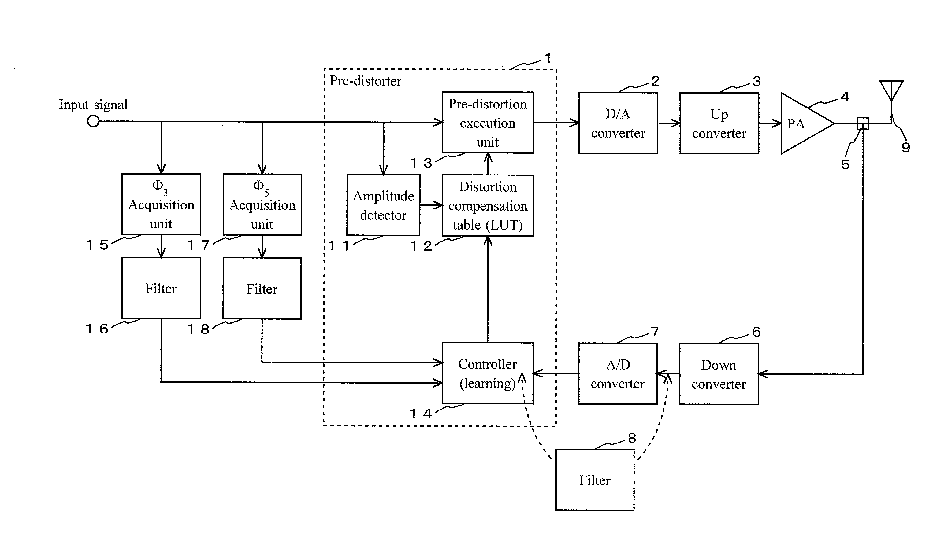
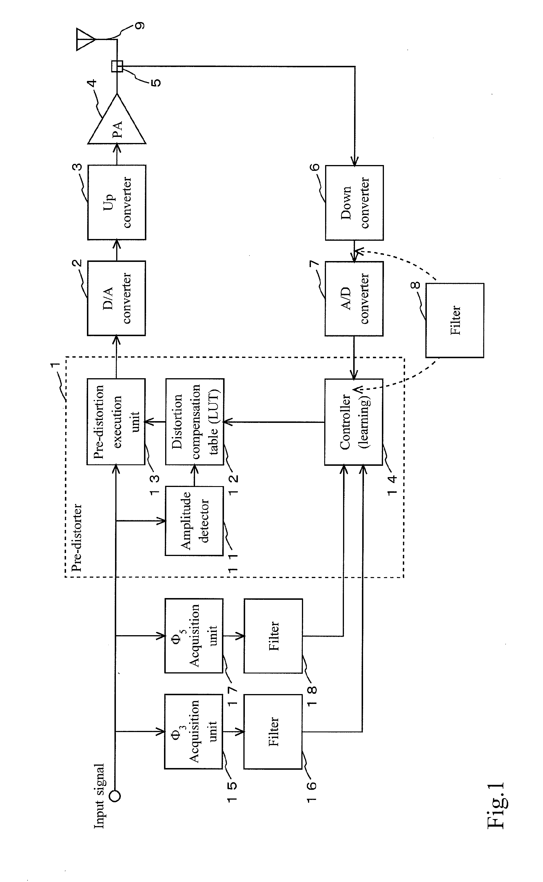
[0250]FIG. 8 shows the configuration of the memory-effect pre-distorter using an expansion in a power series as a reference. It is shown as a principal configuration that the memory-effect pre-distorter according to this embodiment corresponds to the pre-distorter 1 shown in FIG. 1.

[0251]The memory-effect pre-...

third embodiment

[0299]A third embodiment of the invention will be described.

[0300]In this embodiment, a case where both the memoryless pre-distorter and the memory-effect pre-distorter are used in parallel will be described.

[0301]FIG. 9 shows the configuration of a pre-distorter according to an embodiment of the invention.

[0302]The pre-distorter according to this embodiment compensates for the memory effect in addition to the AM-AM conversion and the AM-PM conversion.

[0303]The pre-distorter according to this embodiment includes a memoryless pre-distorter (memoryless PD) 61, a memory-effect pre-distorter (memory-effect PD) 62, an adder 63, and an adder 64. In this embodiment, the memoryless PD 61 and the memory-effect PD 62 are disposed in parallel.

[0304]Here, the configuration having the principle shown in FIG. 4 can be used as the memoryless PD 61 and the configuration having the principle shown in FIG. 8 can be used as the memory-effect PD 62.

[0305]In the pre-distorter according to this embodimen...


PUM


Abstract

It is intended to increase the efficiency of a distortion compensation amplification device having a pre-distorter 1. Level detecting means 11 detects a signal level, correspondence storage means 12 outputs a distortion compensation coefficient depending on the signal level, pre-distortion executing means 13 gives distortion with an inverse characteristic to the signal, filtering means 8 outputs a distortion component from a feedback signal output from an amplifier 4, and correspondence acquiring means 14 updates a learning coefficient constituting a function that gives the inverse characteristic so as to reduce the distortion component. The function that gives the inverse characteristic is expressed using a set of orthogonal polynomials. Each orthogonal function is the total sum of products of functions of the input signal and parameters, and the parameter values are set to cause the orthogonal functions to be orthogonal to each other when functions, which are obtained by applying a filter having the same characteristic as that of the filtering means 8 to the functions of the input signal, are replaced for the functions of the input signal constituting the orthogonal functions.

Description

TECHNICAL FIELD[0001]The present invention relates to a distortion compensation amplification device having a pre-distorter (PD) that compensates for non-linear distortion generated in an amplifier using a pre-distortion method, and more particularly, to a distortion compensation amplification device having a pre-distorter that causes pre-distortion learning coefficients (for example, correspondence given by a function, which is acquired therefrom, that gives an inverse characteristic of a non-linear characteristic of the amplifier) to efficiently converge.BACKGROUND ART[0002]In general, input and output characteristics of a power amplification unit are linear in a region in which an input level is low, and are non-linear in a region in which the input level is greater than a predetermined level, and the output power is finally saturated. Typically, since an operation point close to a saturation point is used to enhance power efficiency of the power amplification unit, non-linear di...

Claims


Application Information

Patent Timeline
IPC IPC(8): H03F1/26
CPCH03F1/3247H03F1/3258H03F3/189H03F3/24H03F2201/3233H03F2201/3209H03F2201/3212H03F2201/3224H03F2200/451
Inventor HONGO, NAOKI
Owner KOKUSA ELECTRIC CO LTD
Why Eureka
Try Eureka