Identification element having an optical transponder

a technology of optical transponders and identification elements, applied in the direction of transmission, transmission systems, indirect connection of subscribers, etc., can solve the problems of card placement directly, unsecure use of radio transponders, and door would be regularly opened by authorised persons, and achieve the effect of low power consumption

Inactive Publication Date: 2011-07-07
REIME GERD
View PDF30 Cites 3 Cited by
  • Summary
  • Abstract
  • Description
  • Claims
  • Application Information

AI Technical Summary

Benefits of technology

[0012]Based on this state of the art, the provides a small optical transponder which has a very low power consumption.
[0014]To this end, use is made of an optical transponder, the transmitter unit of which is a light emitting transmitter unit and the receiver unit of which, if present, is a light receiving receiver unit. Furthermore, an autonomous power supply is provided, wherein the optical transponder and the autonomous power supply that is not a battery are integrated into the identification element. An optical, possibly bi-directional transponder which manages without batteries and has a substantially greater range than the known inductive transponders can thereby be achieved. Moreover, it is preferably programmable from a distance. In addition, an optical solution permits restriction of the transmission angle.
[0015]The optical transponder integrated into the identification element can thus comprise just one transmitter unit or both a transmitter unit and a receiver unit in the event of a need for greater security for example. In both cases, the transmitter unit automatically emits optical signals continuously at least periodically e.g. at a certain frequency or at a certain clock rate i.e. manual operation such as when using an e.g. remote control does not take place. Nevertheless and even despite the continual emission of the optical signals, integration into a relatively small identification element such as a name tag is possible. If the optical transponder only has one transmitter unit, then alternatively, a receiver unit which receives radio waves from its counterpart can also be provided. The transmitter unit of the optical transponder is operated by the control circuit in such a way that it emits optical pulses of less than or equal to 100 nanoseconds several times per second.
[0016]The use of short data words and transmitting times is advantageous for the transmission of information, because the shorter the data word being transmitted or the shorter the transmitting time, the smaller the amount of power that will be needed for the transmission of the data. Shorter transmission times enable interference-free conveyance of information since superimposition of the data words during transmission, when using a plurality of transponders can be prevented in this way.

Problems solved by technology

One disadvantage of these systems is that the card has to be placed directly on the reader every time in order to e.g. open a door.
Transponders utilising radio transmission techniques would guarantee a greater range, but since it is difficult to direct radio waves and, on the other hand, they can also pass through walls and ceilings, the use of a radio transponder is not secure.
Moreover, the door would then be regularly opened quite unintentionally by authorised persons who are e.g. merely passing the door.
Systems operating without manual activation have not been able to enter the market so far because of their size or the weight of the necessary batteries and the associated operating costs.
These devices are therefore provided with a “powerful” battery and are only suitable for sporadic operation.
This can easily happen due to overlap of the temporally relatively long data words.
The employment of the short range communication link does not enable the operator to pass through a door without breaking his stride.

Method used


Image

  • Identification element having an optical transponder
  • Identification element having an optical transponder
  • Identification element having an optical transponder

Examples


Embodiment Construction

[0031]The invention is now described by way of example in more detail with reference to the accompanying drawings. Nevertheless, the exemplary embodiments are only examples which are not intended to limit the inventive concept to a certain arrangement.

[0032]Before the invention is described in detail, it should be pointed out that it is not restricted to the particular components of the device nor to the particular method steps, since these components and processes can vary. The terms used here are merely intended to describe special embodiments and are not used in a restrictive sense. If, moreover, the singular or indefinite articles are used in the description or in the Claims, these also refer to a plurality of these elements insofar as the general context does not make it unambiguously clear that something else is meant.

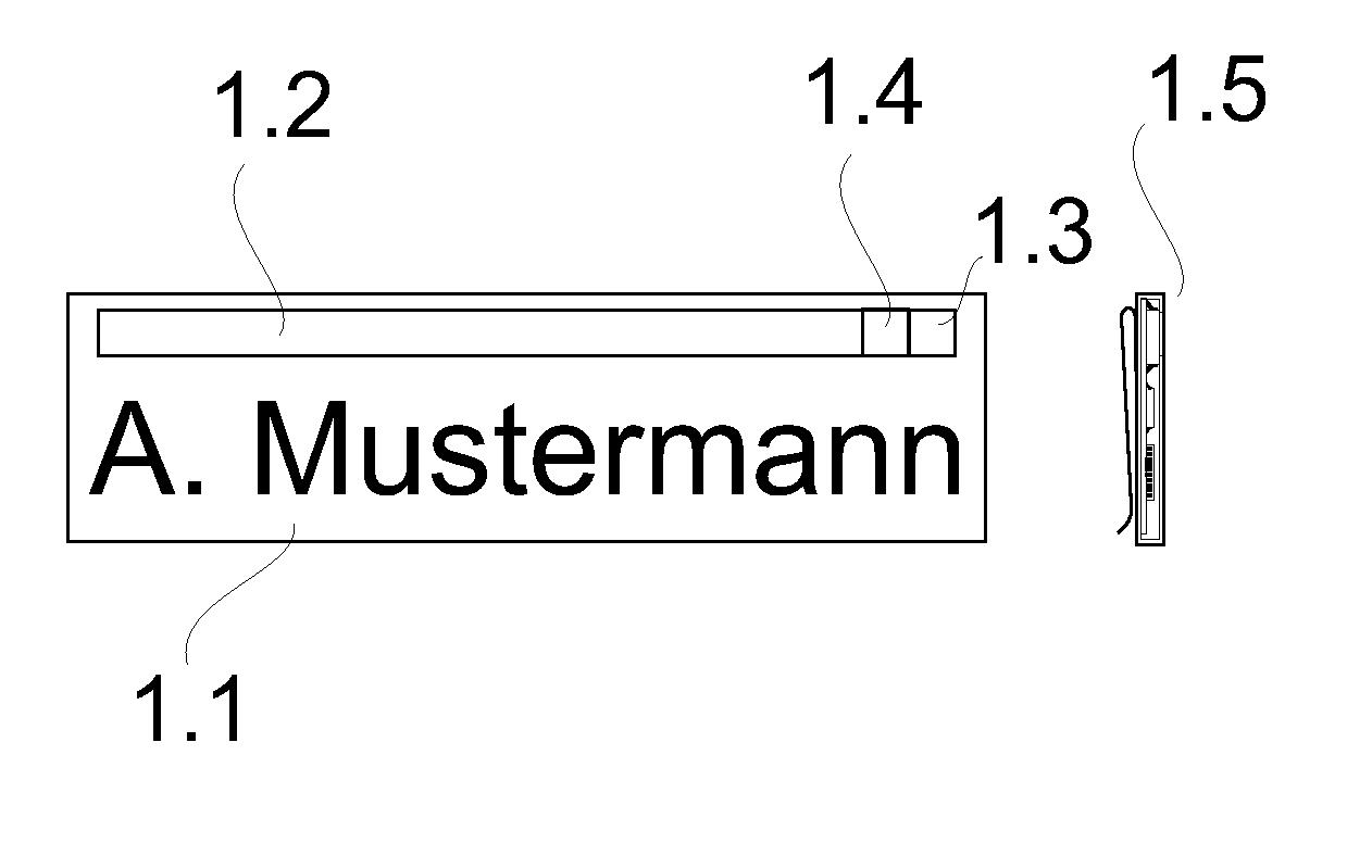
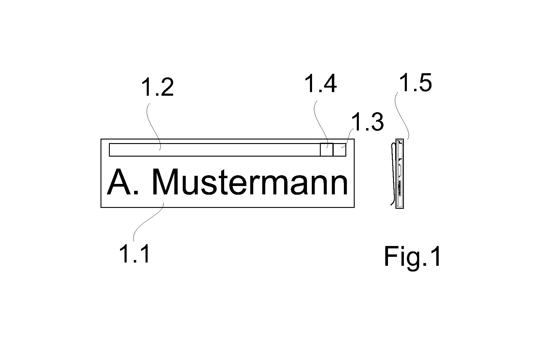
[0033]The Figures and in particular FIG. 1 show an identification element which is preferably in the form of a name tag or an identifying means or identification...


PUM


Abstract

An identification element has a transponder with a data-emitting transmission unit and with a data-receiving reception unit in order to communicate with a device for registering and / or controlling access authorization to spaces or objects. In addition, a control circuit is provided for the transmission unit and reception unit. The transponder is an optical transponder (1.1), the transmission unit of which is a light-emitting transmission unit (1.3) and the reception unit of which is a light-receiving reception unit (1.4). The optical transponder and an autonomous power supply are integrated into the identification element. The identification element is in the shape of a name plate or of an identification element of comparable size which is assigned to an object or body or is to be supported thereon. By virtue of the fact that the transmission unit (1.3) of the optical transponder (1.1) is operated by the control circuit (2.5) in such a way that it transmits optical pulses of less than or equal to 100 nanoseconds repeatedly per second and that the identification element is batteryless, a very small optical transponder is provided which requires little energy and no batteries.

Description

CROSS REFERENCE TO RELATED APPLICATIONS[0001]The present application claims the priority of the German patent applications 10 2008 045 142.8, filed on 1 Sep. 2008, and also 10 2008 050 988.4, filed on 13 Oct. 2008, the published contents of which are hereby expressly incorporated by reference into the subject matter of the present application.TECHNICAL FIELD[0002]The invention relates to an identification element incorporating a transponder and also to a method for recognizing an identification element.BACKGROUND[0003]Inductively working transponders have been known for a long time. They are employed in many cases as access control means e.g. on security doors. A so-called card reader is located in front of the door. In order to enter the secured area, the user has to hold a small authorising element, often in the shape of a cheque card, close to the card reader. Inductive power can be fed into the card due to its close proximity. Thereupon, the card itself inductively conveys a dig...

Claims


Application Information

Patent Timeline
Patent Type & Authority Applications(United States)
IPC IPC(8): G06F7/04H04B10/114
CPCG06K19/0723G06K19/0728H04B10/1143G07C9/00309G07C2009/00785G07C9/00007G07C9/20
Inventor REIME, GERD
Owner REIME GERD
Why Eureka
Try Eureka