Route planning method, route planning device and autonomous mobile device

a technology of route planning and autonomous mobile devices, applied in distance measurement, navigation instruments, instruments, etc., can solve the problems of increasing error, affecting the accuracy of route planning,

Inactive Publication Date: 2011-07-07
MURATA MASCH LTD
View PDF10 Cites 40 Cited by
  • Summary
  • Abstract
  • Description
  • Claims
  • Application Information

AI Technical Summary

Benefits of technology

[0061]Moreover, according to various preferred embodiments of the present invention, it is possible to plan a travel route on which an autonomous mobile device which travels along a travel route can travel more smoothly.

Problems solved by technology

Thus, the actual behavior of an autonomous mobile device is subject to a slight error (response lag) relative to the intended behavior.
Note that this error becomes more prominent as the travel speed increases.
Meanwhile, the clearance (width of passage) of the route on which the autonomous mobile device travels is not always constant.
Thus, with the mobile robot described in Japanese Patent Application Laid-open No. 2007-213111, in cases where the autonomous mobile device passes through, for example, a narrow passage (route) or avoids an obstacle in a narrow passage, there was a possibility that it would come in contact with the obstacle due to the influence of the foregoing error.
Specifically, although the route clearance at the pass-through points on the travel route is often different for each pass-through point, with the foregoing route generation method, it was not possible to comprehend, in advance, the route clearance of each pass-through point on the planned travel route.
Thus, there was a possibility that the generated travel route would not necessarily be a shape that is suitable for the travel of the autonomous mobile device from the perspective of the motion performance (motion characteristics) of the autonomous mobile device.

Method used


Image

  • Route planning method, route planning device and autonomous mobile device
  • Route planning method, route planning device and autonomous mobile device
  • Route planning method, route planning device and autonomous mobile device

Examples


first preferred embodiment

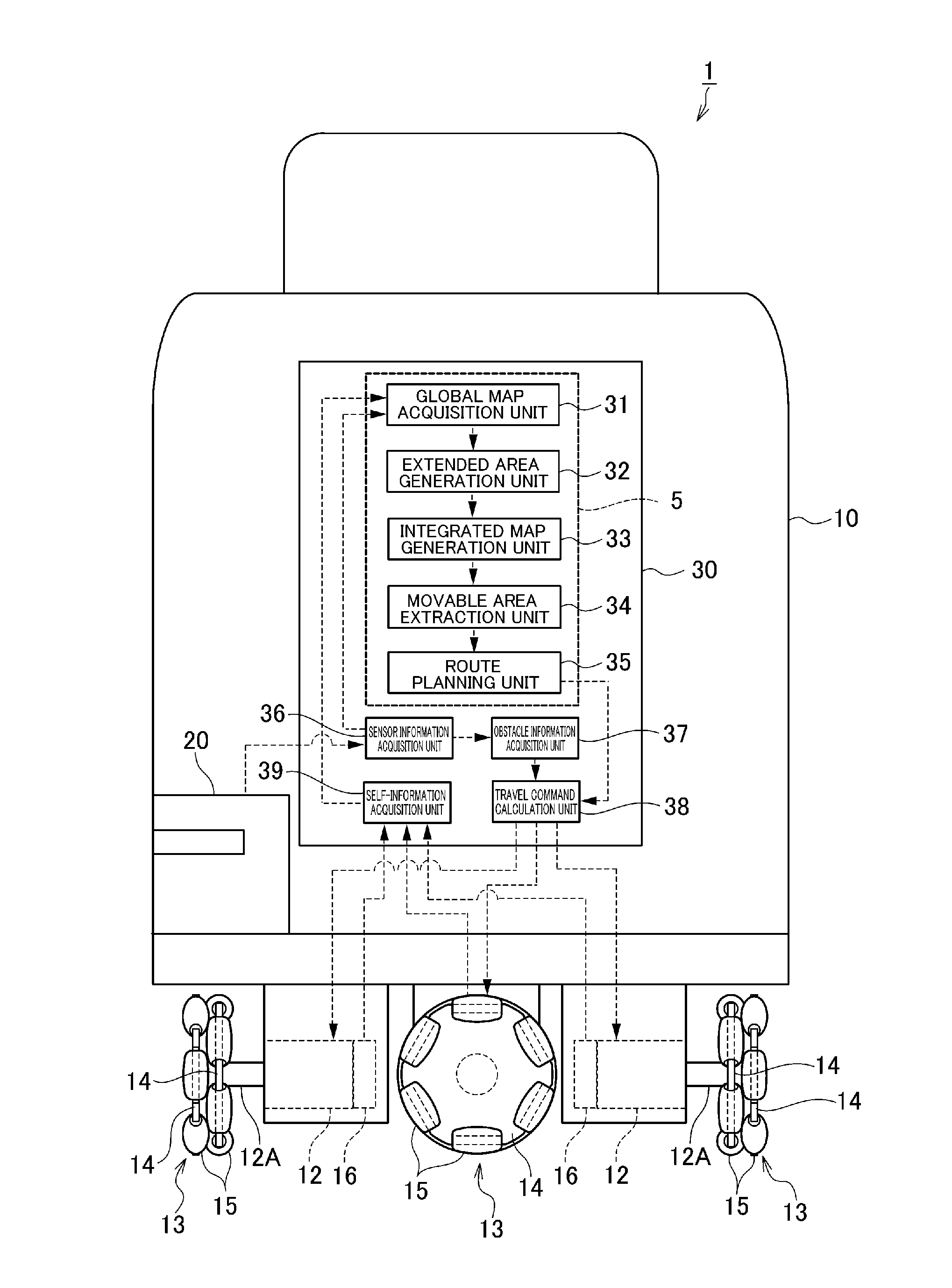
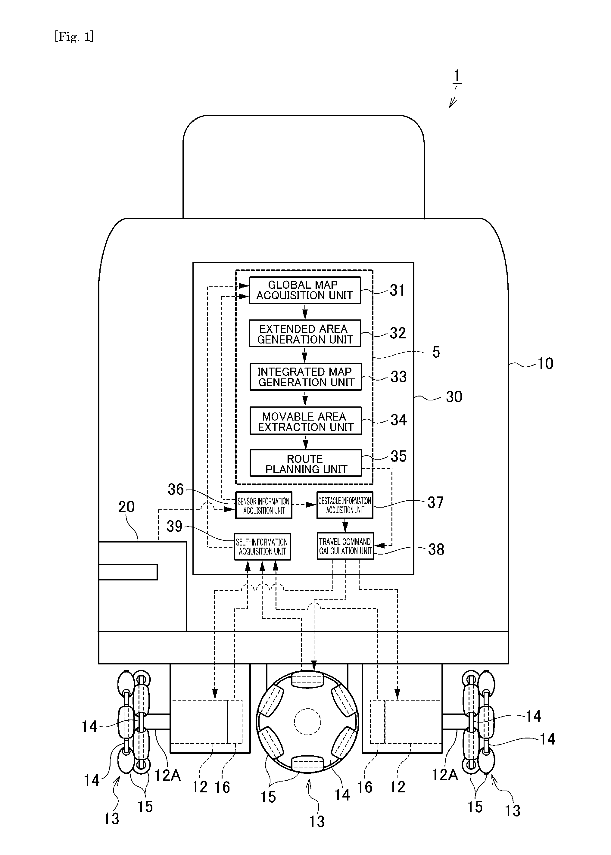
[0093]The configuration of a route planning device 5 and an autonomous mobile device 1 mounted with the foregoing route planning device 5 according to the first preferred embodiment is foremost explained with reference to FIG. 1. FIG. 1 is a functional block diagram showing the configuration of the autonomous mobile device 1 mounted with the route planning device 5.

[0094]The autonomous mobile device 1 performs the functions of acquiring an ambient environmental map (map showing an area containing obstacles and an area that does not contain obstacles; hereinafter referred to as the “global map”), planning a travel route which connects the starting point (starting position) and the destination (goal position) on the global map, and autonomously traveling from the starting position to the goal position along the planned route. Note that the starting position and the goal position are given by the user. Thus, the autonomous mobile device 1 preferably includes a main body 10 provided wit...

second preferred embodiment

[0119]The configuration of a route planning device 6 and an autonomous mobile device 2 mounted with the foregoing route planning device 6 according to the second preferred embodiment is now explained with reference to FIG. 9. FIG. 9 is a block diagram showing the configuration of the autonomous mobile device 2 mounted with the route planning device 6.

[0120]The autonomous mobile device 2 preferably performs the functions of generating an ambient environmental map (map showing an area containing obstacles and an area that does not contain obstacles; hereinafter referred to as the “global map”), planning a travel route which connects the starting point (start point) and the destination (goal point) on the global map given by the user, and autonomously traveling from the start point to the goal point along the planned route. Thus, the autonomous mobile device 2 preferably includes a main body 10 provided with an electric motor 12 at the lower portion thereof and an omni wheel 13 that is...

third preferred embodiment

[0169]The configuration of the autonomous mobile device 3 according to the third preferred embodiment is now explained with reference to FIG. 20. FIG. 20 is a block diagram showing the configuration of the autonomous mobile device 3.

[0170]The autonomous mobile device 3 acquires an ambient environmental map (map showing an area containing obstacles and an area that does not contain obstacles; hereinafter referred to as the “global map”), plans a travel route which connects the starting point (starting position) and the destination (goal position) on the global map given by the user, and acquires the route clearance of the travel route. Moreover, the autonomous mobile device 3 autonomously travels from the starting position to the goal position along the planned travel route, and, upon traveling, performs travel control (for example, adjustment of the travel speed) according to the route clearance of the self location (travel point). Thus, the autonomous mobile device 3 preferably inc...


PUM


Abstract

A route planning device that is capable of comprehending, in advance, a route clearance at a pass-through point on a planned travel route, includes a global map acquisition unit arranged to generate a global map showing an obstacle area in which an obstacle exists, an extended area generation unit arranged to generate an extended obstacle area and three extended area by extending stepwise an outline of the obstacle area contained in the global map, an integrated map generation unit arranged to generate an integrated map by superposing for integration of the extended obstacle area with the three extended areas; a movable area extraction unit arranged to extract a movable area from the integrated map and thinning the same, and a route planning unit arranged to acquire a route clearance at a sub goal according to the extended areas on the integrated map to which the sub goal on the travel route belongs, upon planning the travel route from the thinned movable area.

Description

BACKGROUND OF THE INVENTION[0001]1. Field of the Invention[0002]The present invention relates to a route planning method and a route planning device for planning a travel route, and an autonomous mobile device.[0003]2. Description of the Related Art[0004]A conventional autonomous mobile device autonomously travels from the starting point (starting position) to the destination (goal position) along a planned route while avoiding contact with obstacles. As this kind of autonomous mobile device, a mobile robot (autonomous mobile device) which autonomously controls the travel speed and travel direction according to ambient environmental conditions (ambient brightness and the like, for example) is disclosed in Japanese Patent Application Laid-open No. 2007-213111. This mobile robot travels at a fast speed if the ambient environmental conditions are favorable, and drops its travel speed if the ambient environmental conditions are inferior in order to avoid contact with obstacles.[0005]Mea...

Claims


Application Information

Patent Timeline
Patent Type & Authority Applications(United States)
IPC IPC(8): G05D1/02G01C21/00
CPCG05D1/0272G05D1/0214G05D1/0274G05D1/024G05D1/0217G05D1/02
Inventor TANAKA, SHOJISHITAMOTO, HIDEO
Owner MURATA MASCH LTD
Why Eureka
Try Eureka