Plant analysis system

a plant analysis and plant technology, applied in the field of plant analysis systems, can solve the problems of increasing the per capita workload, increasing the implementation of limited production of diversified products, and difficulty in solving problems and achieving quality improvement within a limited amount of time, and achieve the effect of enhancing the efficiency of work

Inactive Publication Date: 2011-07-07
YOKOGAWA ELECTRIC CORP
View PDF11 Cites 14 Cited by
  • Summary
  • Abstract
  • Description
  • Claims
  • Application Information

AI Technical Summary

Benefits of technology

[0017]It is one of illustrative aspects of the present invention to provide a plant analysis system capable of enhancing efficiency of works by sharing information within a plant.

Problems solved by technology

Further, accompanied by personnel downsizing in the manufacturing field, per capita workload is increased and a production system is changed, thereby increasing implementation of limited production of diversified products.
As a result, there occur various new problems and it is difficult to solve the problem and fulfill quality improvement within a limited amount of time.
Since the people who play individual roles engage in jobs by collecting information individually, it is difficult to share operating information and operating analysis, which are collected by the people with other people who play different roles.
For example, it is difficult to quickly reflect an analysis result at the production improvement work and information dealing with the analysis result, which have been executed by an operation staff and a maintenance staff, on the production maintenance work such as operation monitoring, and so forth that is executed by an operator.
In a direction to the contrary to this, in the case where the operator notices an occurrence of abnormality, while implementing monitoring, it is also difficult to deliver data on the abnormality and processing information on the abnormality to the operation staff and the maintenance staff of the production improvement work side.

Method used


Image

  • Plant analysis system
  • Plant analysis system
  • Plant analysis system

Examples


Embodiment Construction

[0027]The invention is now described with reference to an embodiment wherein a plant analysis system of the invention is applied to a distributed control system.

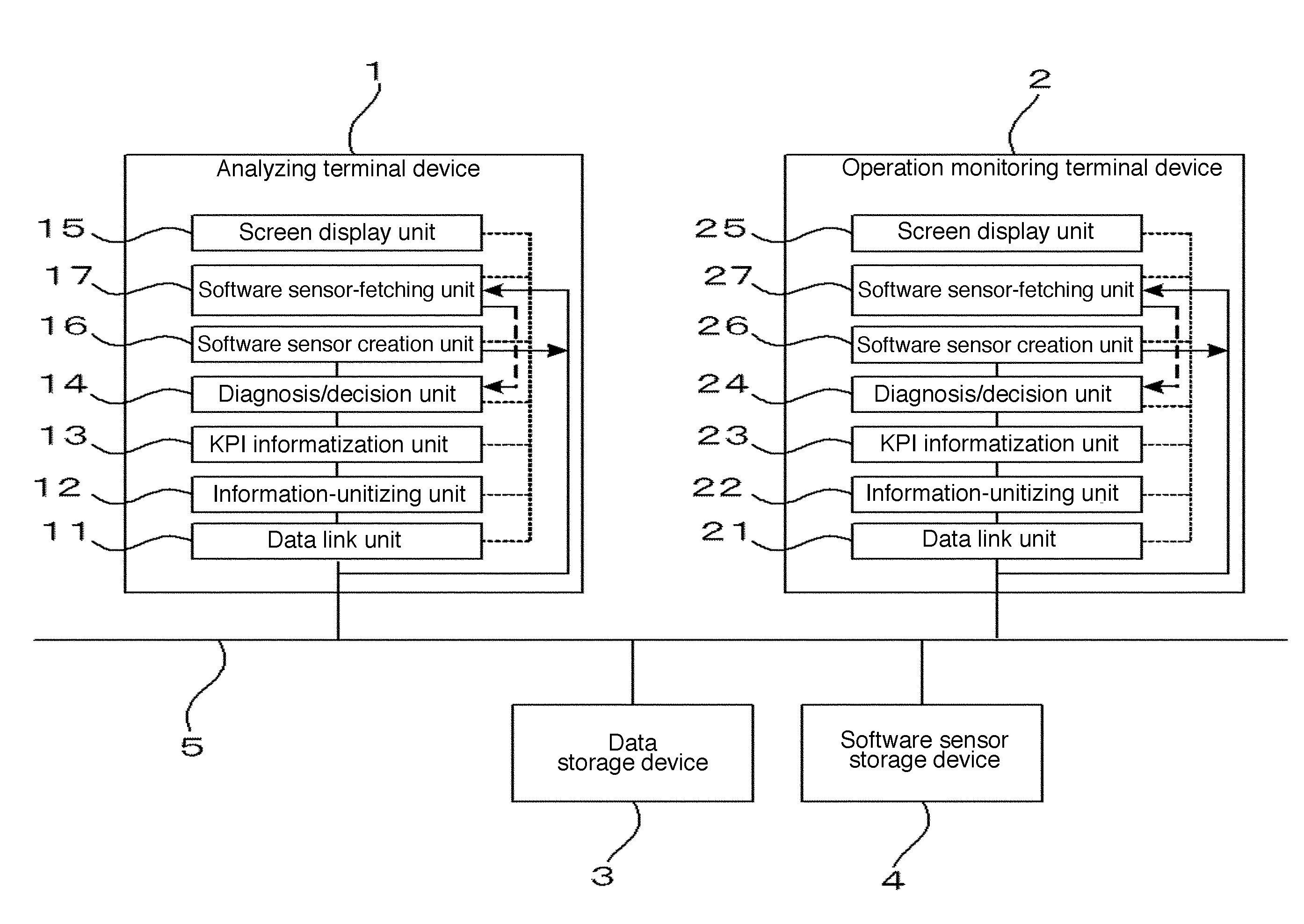
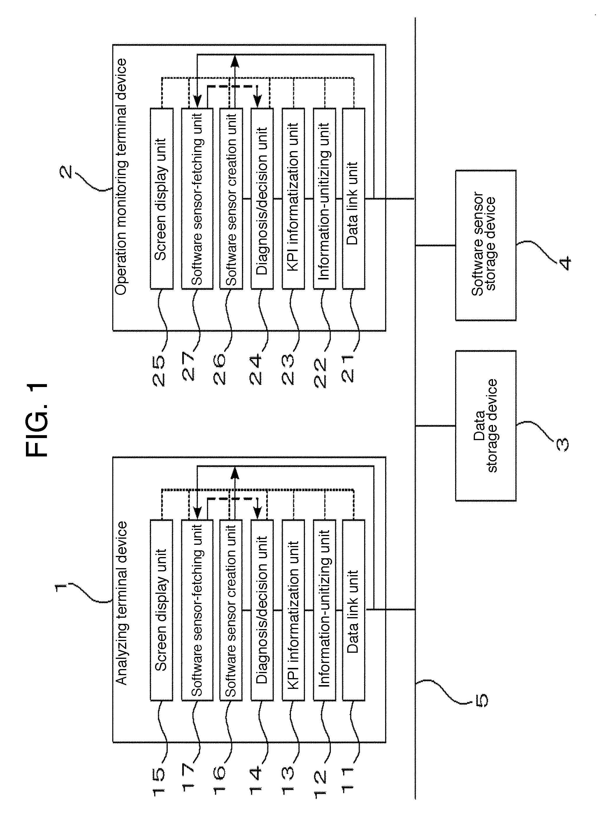
[0028]FIG. 1 is a block diagram showing a configuration of a plant analysis system according to the present embodiment.

[0029]As shown in FIG. 1, the plant analysis system according to the present embodiment comprises a terminal device 1 for analysis (hereinafter referred to as analyzing terminal device 1) for analyzing and diagnosing operation conditions of a plant in the past, a terminal device 2 for operation monitoring (hereinafter referred to as operation monitoring terminal device 2) for monitoring and controlling operation conditions of the plant in real time via field controllers dispersedly disposed in each unit of the plant, a data storage device 3 for storing therein various data, and a software sensor storage device 4 for storing a software sensor, described later.

[0030]Data to be stored in the data storage device...


PUM


Abstract

There is provided a plant analysis system capable of enhancing efficiency of works by sharing information within a plant. A storing means stores a logic defined via a reception means. A monitoring data creation means creates KPI (key performance indicator) in real time as data for monitoring the plant based on data to be acquired from the plant by use of the logic stored in the storing means. An analysis data creation means creates the KPI as analyzing data for analyzing a plant state in the past based on historical data stored in a historical data storage means by use of the logic stored in the storing means.

Description

[0001]This application claims priority from Japanese Patent Application No. 2010-001204, filed on Jan. 6, 2010, the entire contents of which are herein incorporated by reference.BACKGROUND[0002]1. Technical Field[0003]The present invention relates to a plant analysis system for analyzing a plant state based on data acquired from the plant.[0004]2. Related Art[0005]In a process manufacturing industry for manufacturing food products / drinks, chemical products, medical products, petroleum, materials, and so forth, people who engage in operations of a plant comprehend states of processes based on various information collected from various locations so as to stably and safely operate the plant, thereby managing qualities, delivery dates, and so forth of the products.[0006]Further, the people who play individual roles or tasks (e.g. a manager of a manufacturing department, an operation staff, a maintenance staff, an operator and so forth) engage in operations of the plant. The people who p...

Claims


Application Information

Patent Timeline
Patent Type & Authority Applications(United States)
IPC IPC(8): G06Q10/00G05B19/418G05B23/02
CPCG06Q10/0639G05B19/41875Y02P90/02
Inventor SUSUMAGO, MITSUTOSHI
Owner YOKOGAWA ELECTRIC CORP
Why Eureka
Try Eureka