Method and apparatus for disassembling display device

Inactive Publication Date: 2011-07-14
PANASONIC CORP
View PDF2 Cites 3 Cited by
  • Summary
  • Abstract
  • Description
  • Claims
  • Application Information

AI Technical Summary

Benefits of technology

[0022]In this method, when the attaching member is cut by the cutting device and the electric circuit member is detached and separated from the chassis member, the tilt angle of the stage can be adjusted in response to the load by the tilt angle adjusting device. Therefore, even when attaching members of the electric circuit member are irregularly scattered, by adjusting the tilt angle of the stage in response to the load during cutting, a certain load can be applied to the cutting device by the own weight of the display device, and stable cutting is allowed. Thus, even when a large display device with a large screen is disassembled, a cutting failure or cutting time loss can be reduced, and an efficient and high-quality disassembling process of a PDP can be achieved.
[0029]In this configuration, when the attaching member is cut by the cutting device and the electric circuit member is detached and separated from the chassis member, the tilt angle of the stage can be adjusted in response to the load by the tilt angle adjusting device. Therefore, even when attaching members of the electric circuit member are irregularly scattered, by adjusting the tilt angle of the stage in response to the load during cutting, a certain load can be applied to the cutting device by the own weight of the display device, and stable cutting is allowed.

Problems solved by technology

Therefore, an excessive peeling force needs to be applied when they are separated from each other in the disassembling process.
It therefore becomes difficult to take a physical action uniformly over the whole surface of a large display device.
Disadvantageously, the glass substrate forming the PDP breaks, the productivity in a subsequent process of separating the glass substrate is reduced, or a failure occurs in recovering the material.
When the attaching member disposed in the metal plate is cut in order to separate and disassemble the electric circuit substrate from the metal plate of the chassis member, the load during cutting is un-uniform because the attaching member is arranged irregularly on the metal plate.
Therefore, a cutting failure or cutting time loss occurs, the productivity and efficiency reduce in disassembling the display device, disadvantageously.

Method used


Image

  • Method and apparatus for disassembling display device
  • Method and apparatus for disassembling display device
  • Method and apparatus for disassembling display device

Examples


first exemplary embodiment

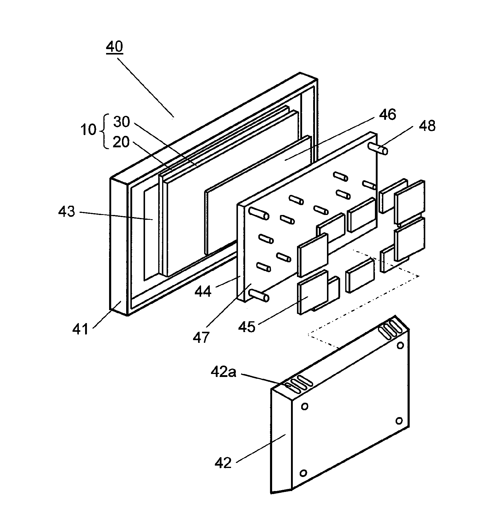
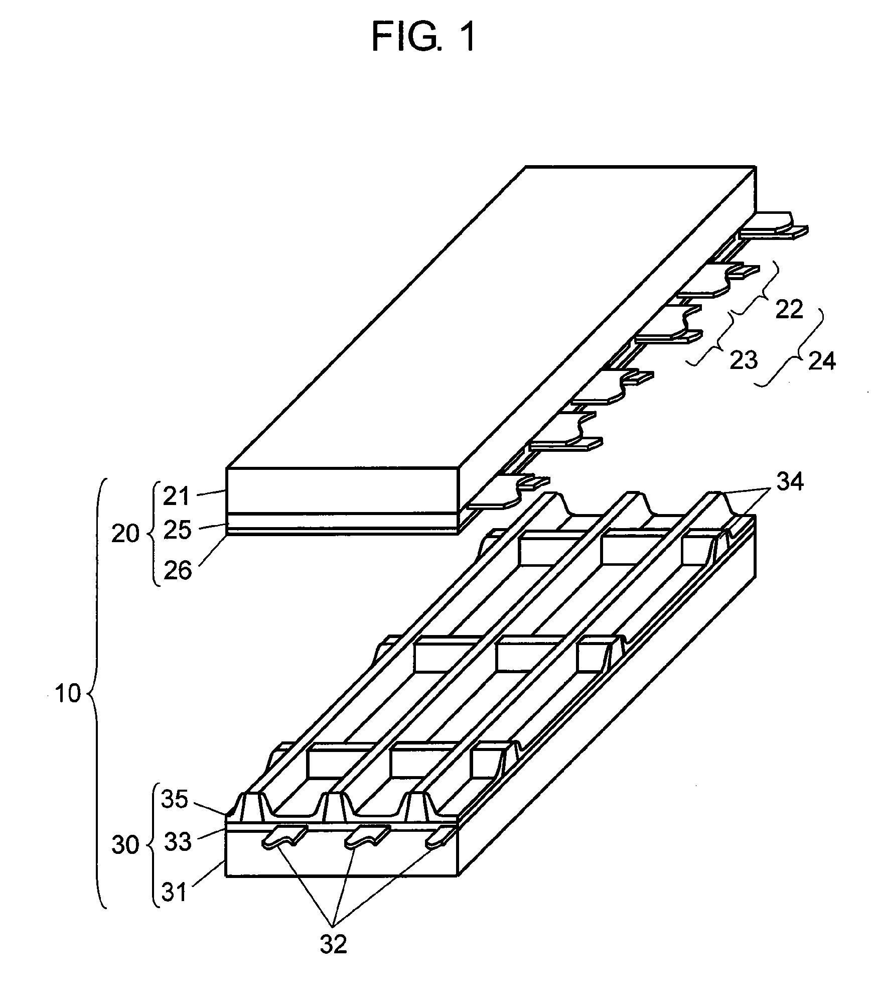
[0084]FIG. 1 is an exploded perspective view showing a fundamental structure of a PDP used in a plasma display device employing a disassembling method of a display device in accordance with a first exemplary embodiment of the present invention. PDP 10 is formed of front plate 20 and back plate 30. Front plate 20 has front glass substrate 21, and a plurality of display electrode pairs 24 formed of scan electrodes 22 and sustain electrodes 23 are disposed in parallel on front glass substrate 21. Dielectric layer 25 is formed so as to cover scan electrodes 22 and sustain electrodes 23, and protective layer 26 is formed on dielectric layer 25.

[0085]Back plate 30 has back glass substrate 31, and a plurality of data electrodes 32 are formed in parallel on back glass substrate 31. Base dielectric layer 33 is formed so as to cover data electrodes 32, and mesh barrier ribs 34 are formed on dielectric layer 33. Phosphor layers 35 for sequentially emitting lights of respective colors of red, g...

second exemplary embodiment

[0123]FIG. 7 is a diagram showing a disassembling method of a display device in accordance with a second exemplary embodiment of the present invention.

[0124]In FIG. 7, in disassembling apparatus 100, support section 106 of stage 102 is disposed in a central part of stage 102, and the weight of stage 102 is set greater than that of metal plate unit 49. Therefore, the weight can be kept in balance with respect to variation in the tilt angle of stage 102, and the power for controlling the tilt angle can be reduced.

[0125]Disassembling apparatus 100 has added heavy object 107a or added heavy object 107b for increasing the abutting force at which metal plate unit 49 as a panel member abuts on saw blade 103a as the cutting device. Added heavy object 107a may press down metal plate unit 49, or added heavy object 107b shown by dotted line may be suspended on the saw blade 103a side to pull down metal plate unit 49.

[0126]In these disassembling methods, a predetermined weight is applied to met...

third exemplary embodiment

[0130]FIG. 8A and FIG. 8B are diagrams showing a disassembling method of a display device in accordance with a third exemplary embodiment of the present invention. In disassembling apparatus 100 using the disassembling method of the display device in accordance with the third exemplary embodiment, discharge section 109 for specifying discharge of disassembled and separated circuit boards 45 is disposed on stage 102.

[0131]FIG. 8A and FIG. 8B show the case that PDP 10 and metal support plate 44 are mounted on stage 102 in an integrated state through joint member 46, and the case that metal support plate 44 is separated from circuit boards 45 from this state. Discharge section 109 is disposed near saw blade 103a, and is arranged so as to make the relative distance to saw blade 103a constant. Discharge section 109 has tilt plate 111 so that the discharge direction of circuit boards 45 separated by cutting of attaching members 48 by saw blade 103a is specified and circuit boards 45 are g...


PUM

PropertyMeasurementUnit
Weightaaaaaaaaaa
Forceaaaaaaaaaa
Angleaaaaaaaaaa

Abstract

In the disassembling method of a display device of the present invention, the display device has a display panel, and metal plate unit having a panel member formed of a chassis member disposed on the back surface of the display panel and a circuit board as an electric circuit member attached to the chassis member through an attaching member. The disassembling method has a mounting step of mounting metal plate unit on stage whose tilt angle can be adjusted by mechanism section and a cutting step of cutting the attaching member in parallel with the surface of stage with saw blade that abuts on the attaching member by the own weight of metal plate unit based on the tilt angle of stage.

Description

TECHNICAL FIELD[0001]The present invention relates to a method and apparatus for disassembling display device, and more particularly to a disassembling method and disassembling apparatus capable of easily separating an electric circuit member from a chassis member in a short time in a plasma display device or the like having a metal plate such as the chassis member on its back surface.BACKGROUND ART[0002]Recently, as a display device appropriate to thinning and enlargement, liquid crystal display devices using a liquid crystal display panel and plasma display devices using a plasma display panel (hereinafter referred to as “PDP”) have received attention and have been mass-produced, and the sale of them has hugely expanded.[0003]A PDP is formed of a pair of glass substrates of a front plate and a back plate. The front plate has a display electrode pair, a dielectric layer, and a protective layer on the front glass substrate. The back plate has a data electrode, a barrier rib, and a p...

Claims


Application Information

Patent Timeline
IPC IPC(8): H05K13/00
CPCB09B5/00B23D55/046Y10T29/49169Y10T29/49002Y10T29/49135Y10T29/49202Y10T29/49199Y10T29/49155Y10T29/49004
Inventor TANI, YOSHIYUKIIWAMOTO, HIROSHI
Owner PANASONIC CORP
Why Eureka
Try Eureka