Exhaust heat recovery system

a heat recovery system and exhaust heat technology, applied in steam engine plants, combustion engines, machines/engines, etc., can solve the problems of reducing and achieve the effect of optimizing the operation and preventing the reduction of the efficiency of the refrigerant pump

Inactive Publication Date: 2011-07-14
MITSUBISHI ELECTRIC CORP
View PDF19 Cites 34 Cited by
  • Summary
  • Abstract
  • Description
  • Claims
  • Application Information

AI Technical Summary

Benefits of technology

[0006]According to the present invention, because by using the temperature adjusting means the pressure inside the refrigerant tank can be adjusted by adjusting the temperature inside the refrigerant tank, even if the pressure difference in the Rankine cycle is small, the refrigerant filling amount in the Rankine cycle can be adjusted depending on the super-cooling degree. Therefore, a nonconventional remarkable effect can be obtained that, even in starting of operation of the Rankine cycle, the efficiency of the refrigerant pump can be prevented from decreasing, and an exhaust heat recovery system capable of performing optimized operation can be obtained.

Problems solved by technology

In a conventional exhaust heat recovery system using a Rankine cycle, because super-cooling degree of operating fluid (hereinafter, referred to as refrigerant) varies during an operation caused by variation of outside air temperature or by fluctuation of condensation capacity of a condenser, a problem has occurred that efficiency of a refrigerant pump decreases.

Method used


Image

  • Exhaust heat recovery system
  • Exhaust heat recovery system
  • Exhaust heat recovery system

Examples


embodiment 1

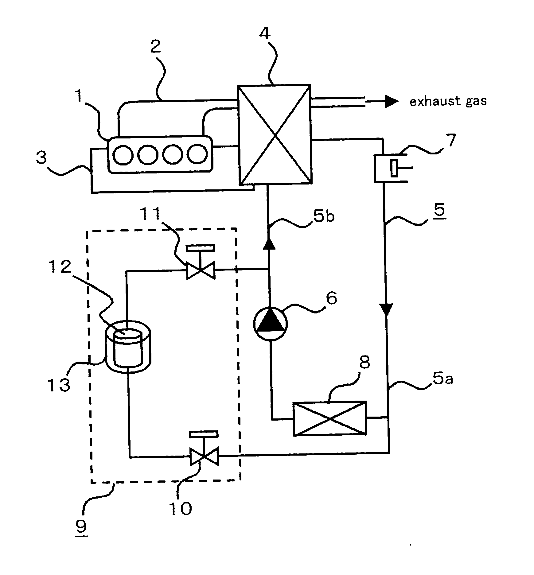
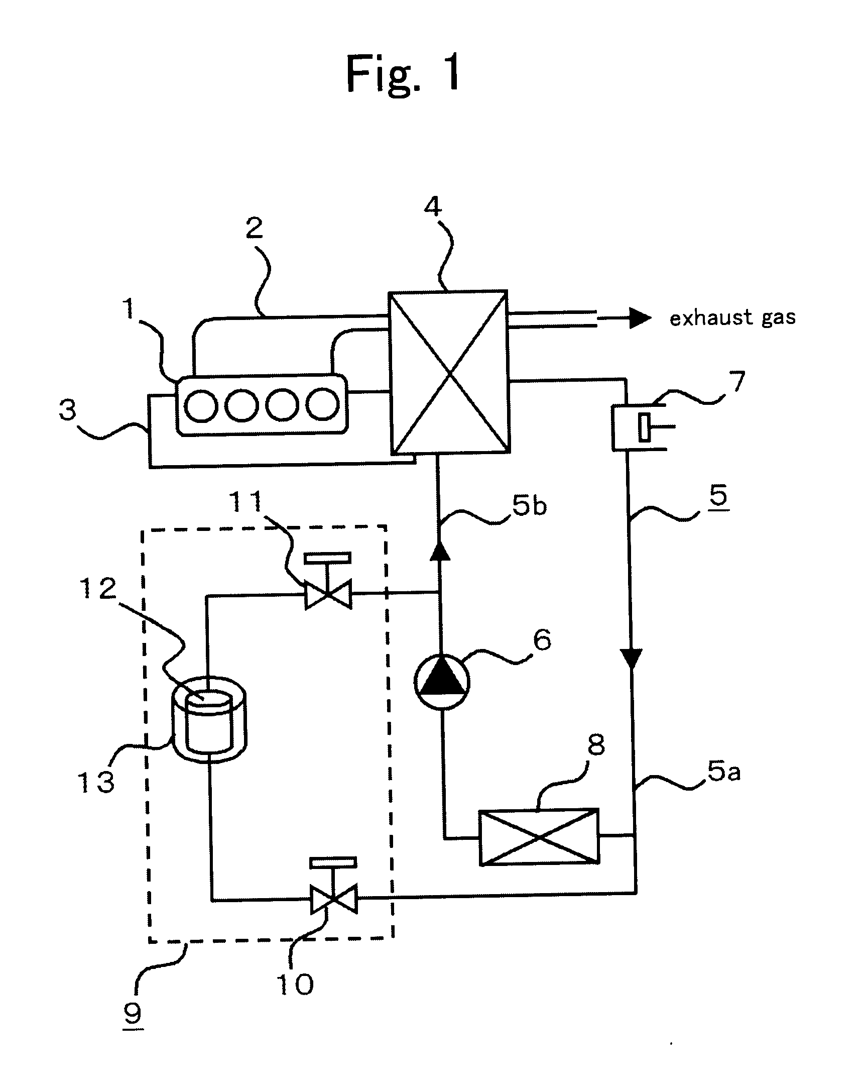
[0023]FIG. 1 is a configuration view representing an exhaust heat recovery system in Embodiment 1 of the present invention. In Embodiment 1, the exhaust heat recovery system according to the present invention is applied to an engine 1 for an automobile (hereinafter, referred to as an engine 1). The engine 1 is an internal-combustion engine that generates driving force for running. An exhaust pipe 2 exhausts combustion gas (exhaust gas) exhausted from the engine 1 to the atmosphere. In a cooling water circuit 3, engine cooling water is circulated by a cooling water pump (not illustrated).

[0024]A Rankine cycle 5 is configured with a closed circuit in which a cooling-water / exhaust-gas heat exchanger 4, an expander 7, a condenser 8, and a refrigerant pump 6 are sequentially connected. In this closed circuit, a flow route, along a refrigerant-flow direction, from the expander 7 to the refrigerant pump 6 through the condenser 8 is called as a low-pressure circuit portion 5a, while that fr...

embodiment 2

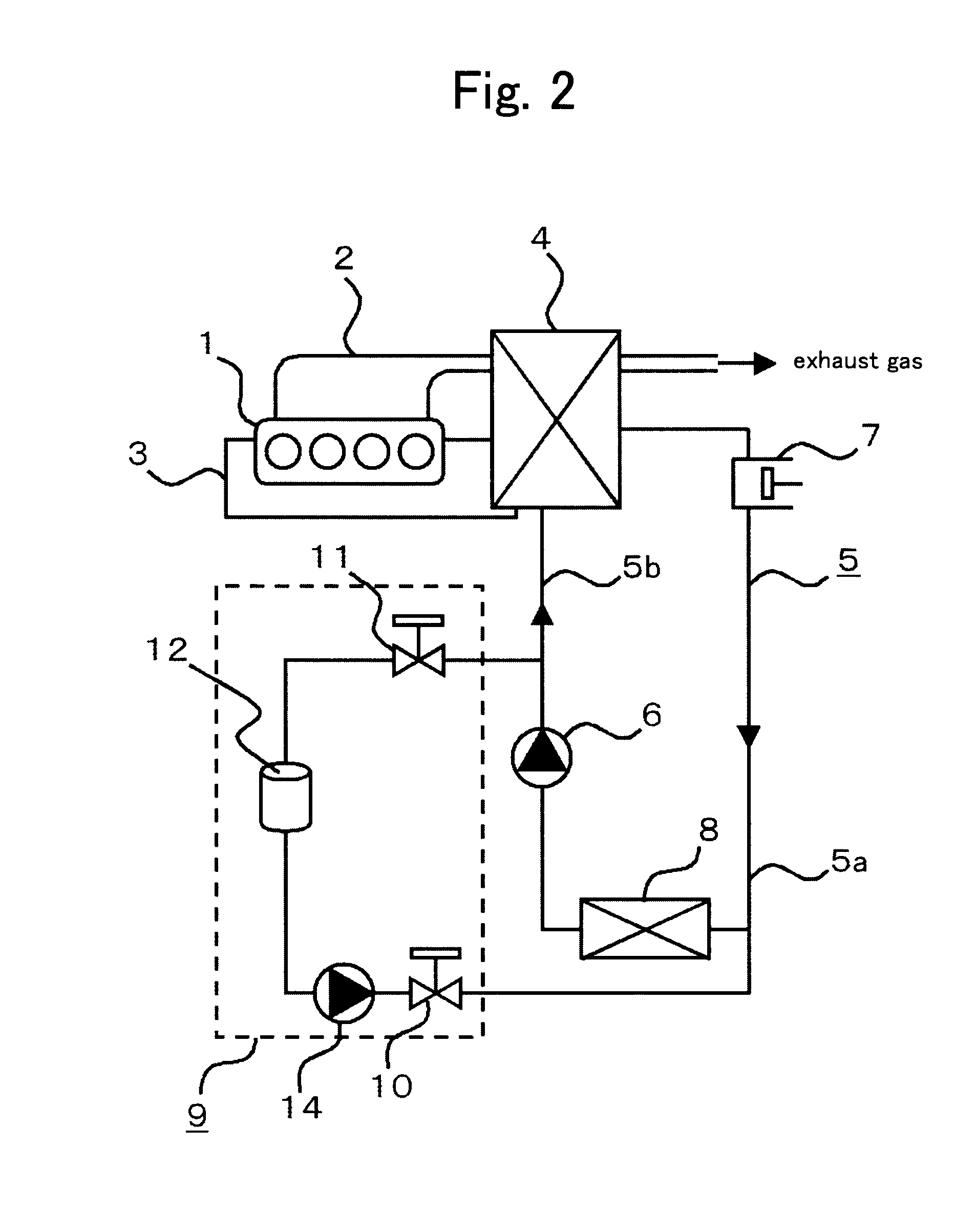
[0038]In Embodiment 1, the temperature adjusting means 13 is used as the refrigerant filling method from the refrigerant tank 12 to the Rankine cycle 5; however, in Embodiment 2, a refrigerant carrying means provided in the refrigerant-filling-amount adjuster 9 is used. FIG. 2 is a configuration view illustrating an exhaust heat recovery system according to Embodiment 2 of the present invention. The refrigerant-filling-amount adjuster 9 according to Embodiment 2 of the present invention is explained referring to FIG. 2. Hereinafter, the system is explained using a refrigerant pump 14 as the refrigerant carrying means.

[0039]In the low-pressure circuit portion 5a, the low-pressure-side valve 10 is connected to the inlet side of the condenser 8 by the pipe. This low-pressure-side valve 10 is closed in a steady state. The low-pressure-side valve 10 is connected by the pipe through the refrigerant pump 14 to a liquid layer portion of the refrigerant inside the refrigerant tank 12.

[0040]W...

embodiment 3

[0045]In Embodiment 3, an operation of the exhaust heat recovery system when the Rankine cycle 5 stops operating is explained. The configuration of the exhaust heat recovery system according to Embodiment 3 is similar to that in Embodiment 1 or Embodiment 2; therefore, its explanation is omitted.

[0046]In the exhaust heat recovery system according to Embodiment 3, when stopping the Rankine cycle 5, by opening the low-pressure-side valve 10, the refrigerant stored in the refrigerant tank 12 is injected into the Rankine cycle 5, and then the system is stopped. Alternatively, after the Rankine cycle 5 has stopped (while the Rankine cycle 5 is suspended), the refrigerant stored in the refrigerant tank 12 is injected into the Rankine cycle 5. Here, the refrigerant filling amount in the Rankine cycle 5 reaches the maximum value, or a value more than a predetermined amount. Here, the predetermined amount is a refrigerant filling amount at which the Rankine cycle 5 can start to operate (that...


PUM


Abstract

In a case of a refrigerant amount being short when a Rankine cycle starts operating, because the pressure difference does not occur across a refrigerant pump, refrigerant cannot be injected from a bypass circuit to the Rankine cycle, and therefore super-cooling degree cannot be controlled. An exhaust heat recovery system is provided that can adjust the super-cooling degree even in the case of the pressure difference not occurring across the refrigerant pump. The system includes a refrigerant tank, for storing refrigerant, which is connected by pipes to the low-pressure circuit side and the high-pressure circuit side of the Rankine cycle through a low-pressure-side valve and a high-pressure-side valve, respectively, and a temperature adjuster for adjusting internal temperature of the refrigerant tank.

Description

TECHNICAL FIELD[0001]The present invention relates to an exhaust heat recovery system for recovering, by a Rankine cycle, exhaust heat from an internal-combustion engine such as an engine for an automobile to power, etc.BACKGROUND ART[0002]In a conventional exhaust heat recovery system using a Rankine cycle, because super-cooling degree of operating fluid (hereinafter, referred to as refrigerant) varies during an operation caused by variation of outside air temperature or by fluctuation of condensation capacity of a condenser, a problem has occurred that efficiency of a refrigerant pump decreases. In order to solve this problem, an outlet side of the refrigerant pump and an inlet side of the condenser are communicated together through a bypass passage, and respective open / close valves are also provided at a high pressure side and a low pressure side of the bypass passage; thereby, by suitably opening or closing the open / close valve depending on the super-cooling degree at the outlet...

Claims


Application Information

Patent Timeline
Patent Type & Authority Applications(United States)
IPC IPC(8): F01K23/10
CPCF01K13/02F01K23/065Y02T10/166F02G5/02F01K25/10Y02T10/12
Inventor TSUCHINO, KAZUNORIKAWAJIRI, KAZUHIKOSATO, MINORU
Owner MITSUBISHI ELECTRIC CORP
Why Eureka
Try Eureka