Trigger switch and electric tool provided therewith

a technology of trigger switch and electric tool, which is applied in the direction of portable power-driven tools, drilling machines, manufacturing tools, etc., can solve the problems of rainwater entering the work area during work to generate a short circuit, adverse effect on the contact mechanism, strange manipulation feeling, etc., and achieves easy assembling work and easy elastic deformation

Active Publication Date: 2011-07-14
ORMON CORP
View PDF16 Cites 27 Cited by
  • Summary
  • Abstract
  • Description
  • Claims
  • Application Information

AI Technical Summary

Benefits of technology

[0019]According to the present embodiment, because the filter is easily...

Problems solved by technology

However, when the dust-resistant structure proposed in Japanese Patent Publication No. 6-18092 is applied to the trigger switch, the dust and water invade easily into the trigger switch from the micro-grooves by pumping action caused by a manipulation of a trigger, which possibly causes the adverse effect on a contact mechanism.
For examp...

Method used


Image

  • Trigger switch and electric tool provided therewith
  • Trigger switch and electric tool provided therewith
  • Trigger switch and electric tool provided therewith

Examples


first embodiment

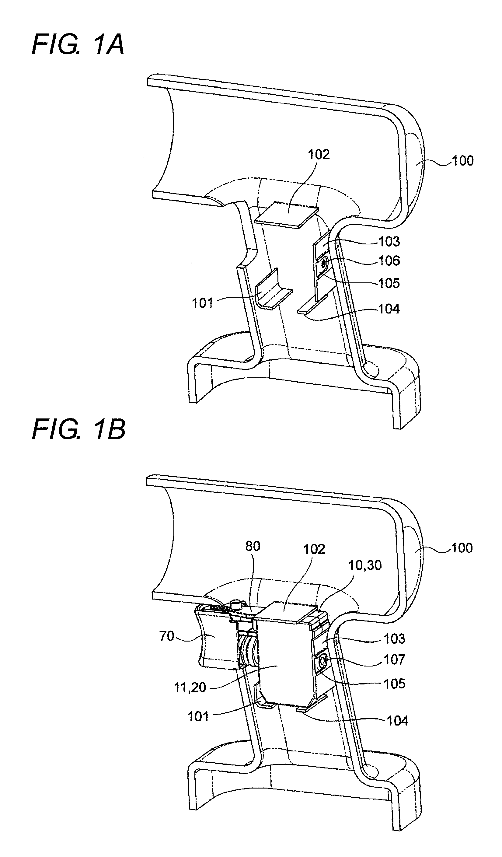
[0032]A trigger switch according to the invention is applied to an electric drill as shown in FIGS. 1 to 5.

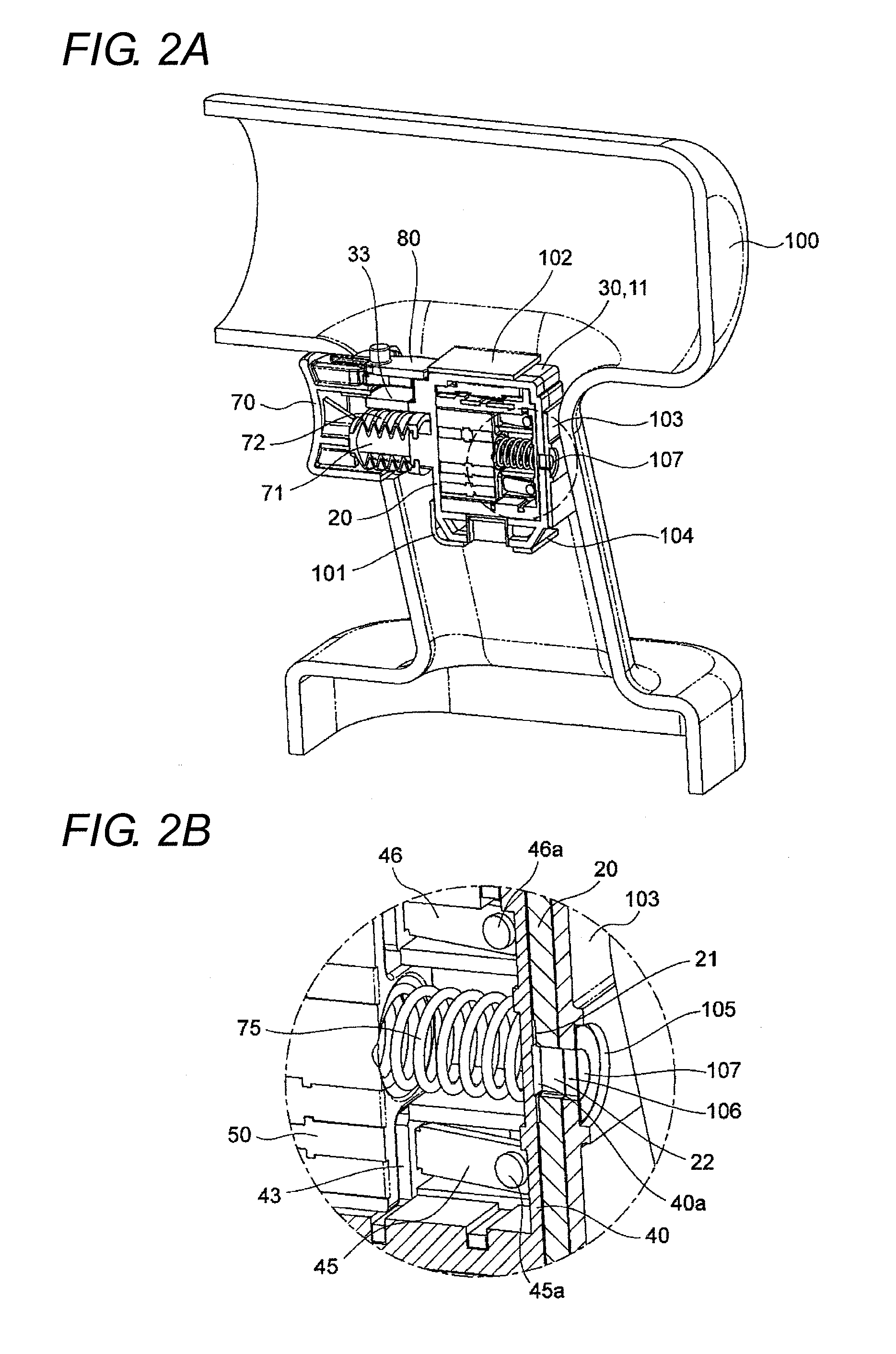
[0033]As shown in FIGS. 1 and 2, a trigger switch 10 is assembled in positioning ribs 101, 102, 103, and 104 that are projected from an inner peripheral surface of a casing 100 on one side of the electric drill. Particularly a venthole 106 is made on depth side of a shallow-groove-shaped step 105 provided in an outward surface of the rib 103 while covered with a filter 107. The rib 103 comes in surface contact with a side face of the trigger switch 10, the venthole 106 made in the rib 103 is located at a position corresponding to a venthole 22 made in the trigger switch 10, and the venthole 106 and the venthole 22 are communicated with each other.

[0034]The filter 107 has a ventilation property, a water-resistant property, and a dust-resistant property. A microfilter in which water vapor (diameter of 0.0004 μm) can pass therethrough while rainwater (100 μm to 3000 μm) does not p...

second embodiment

[0061]As shown in FIG. 6, in the trigger switch 10 of the second embodiment, a micro-porous elastic body 108 that is of the filter is assembled in a step 40c provided in a bottom surface of the base 40, the internal air is caused to flow out from a gap between the bonding surfaces of the first cover 20 and second cover 30, thereby securing the ventilation property.

[0062]That is, in the second embodiment, an elastic engagement portion 25 of the first cover 20 and an engagement bracket 34 of the second cover 30 are engaged in each other and temporarily joined. Then the bonding surfaces of the first and second covers 20 and 30 are integrated by performing the ultrasonic welding or laser welding to a welding rib 26 provided in the first cover 20 shown in FIG. 11.

[0063]However, the bonding surfaces of the first cover 20 and second cover 30, which are located near the step 40c provided in the bottom surface of the base 40, are not integrally welded, but are simply fitted as shown in FIG. ...


PUM

PropertyMeasurementUnit
Lengthaaaaaaaaaa
Lengthaaaaaaaaaa
Flexibilityaaaaaaaaaa

Abstract

An electric tool has a rib projecting from an inner peripheral surface of the electric tool, and a trigger switch. The trigger switch has a housing having a housing venthole, a contact mechanism disposed in the housing, and a trigger that, when depressed into the housing, drives the contact mechanism. The housing of the trigger switch is bonded to the rib. The rib has a rib venthole. The housing venthole is communicated with the rib venthole. The rib venthole is covered with a filter.

Description

BACKGROUND OF THE INVENTION[0001]1. Technical Field[0002]The present invention relates to a trigger switch used in an electric tool and the like.[0003]2. Related Art[0004]Conventionally, for example, Japanese Patent Publication No. 6-18092 proposes that a seal material is bonded to a case of which micro-grooves are provided in a surface so as to prevent an adverse effect of expansion of air and an adverse effect of dust and the like on a switch. However, when the dust-resistant structure proposed in Japanese Patent Publication No. 6-18092 is applied to the trigger switch, the dust and water invade easily into the trigger switch from the micro-grooves by pumping action caused by a manipulation of a trigger, which possibly causes the adverse effect on a contact mechanism. For example, in the trigger switch, there is a risk that rainwater invades during work to generate a short circuit. In order to prevent the adverse effect, there is also made a proposal that bonding surfaces of cover...

Claims


Application Information

Patent Timeline
IPC IPC(8): B25F5/02
CPCH01H13/06H01H9/047
Inventor KOBAYASHI, MINORUBABA, YOSHIYUKIKAMIHASHI, YASUSHI
Owner ORMON CORP
Why Eureka
Try Eureka