Thin illuminated keyboard

a keyboard and illuminated technology, applied in the direction of lighting device details, lighting and heating apparatus, electrical apparatus, etc., can solve the problems of increasing total power consumption, users are difficult to identify the character symbol on each keycap in such a condition, and difficulty in condense light to the area where light is needed, etc., to achieve the effect of a thinner structur

Inactive Publication Date: 2011-07-14
ZIPPY TECH
View PDF10 Cites 18 Cited by
  • Summary
  • Abstract
  • Description
  • Claims
  • Application Information

AI Technical Summary

Benefits of technology

[0006]The primary object of the present invention is to provide an illuminated keyboard with a thinner structure to confine light in the interior of the keyboard and project the light to preset locations to solve the problem of light scattering occurred to the conventional thin illuminated keyboards.
[0008]The thin illuminated keyboard of the invention thus formed provides features as follows: first, the first and second circuit layers are respectively integrated with the first light guide layer and second light guide layer, hence can significantly reduce total thickness and size of the keyboard; second, with the optical passage formed between the first mask layer and second reflection layer, light scattering can be prevented to make use of the light more effective; moreover, the light penetration zone can confine the light to be emitted in a local area of the keycap to condense light projection.

Problems solved by technology

Such a light guide structure makes the light scatter outside from the circuit board, and is difficult to condense the light to the area where the light is needed.
Moreover, users are difficult to identify the character symbol on each keycap in such a condition.
As a result, total power consumption increases and a greater amount of heat is generated.

Method used


Image

  • Thin illuminated keyboard
  • Thin illuminated keyboard
  • Thin illuminated keyboard

Examples


first embodiment

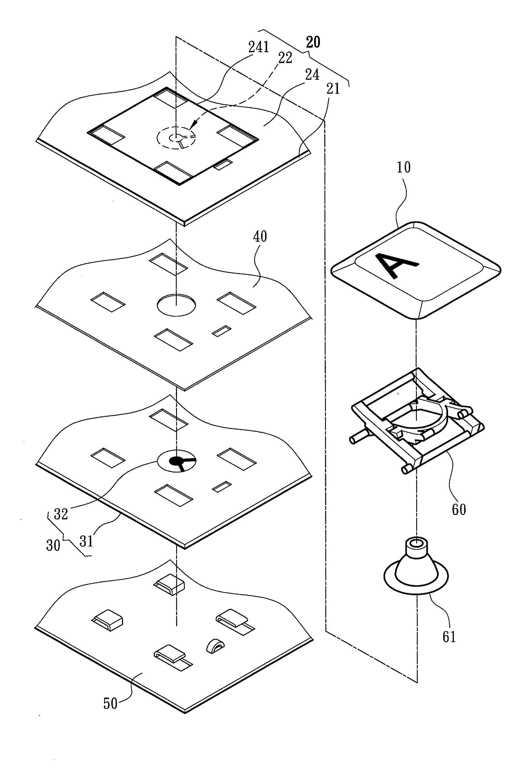
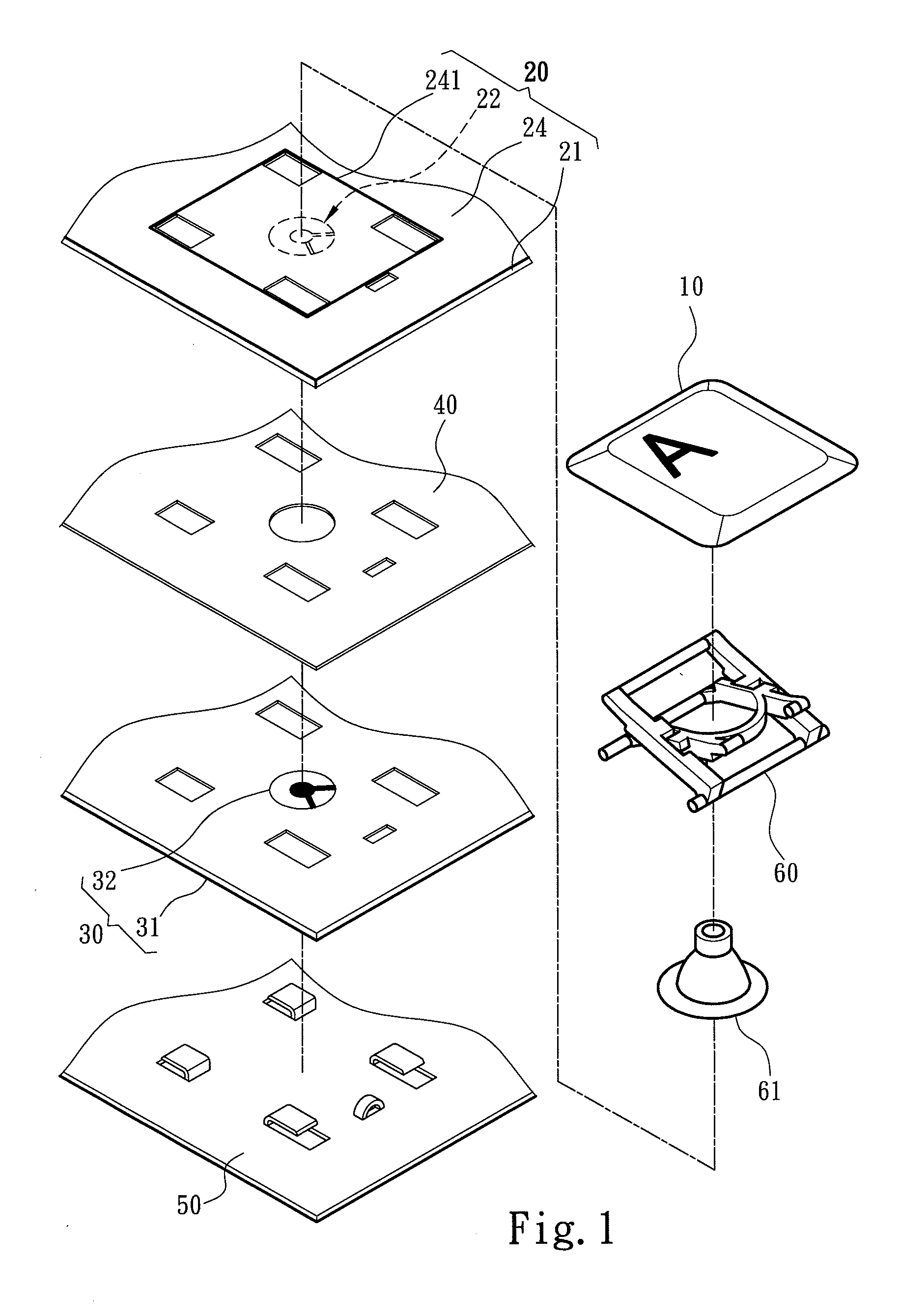
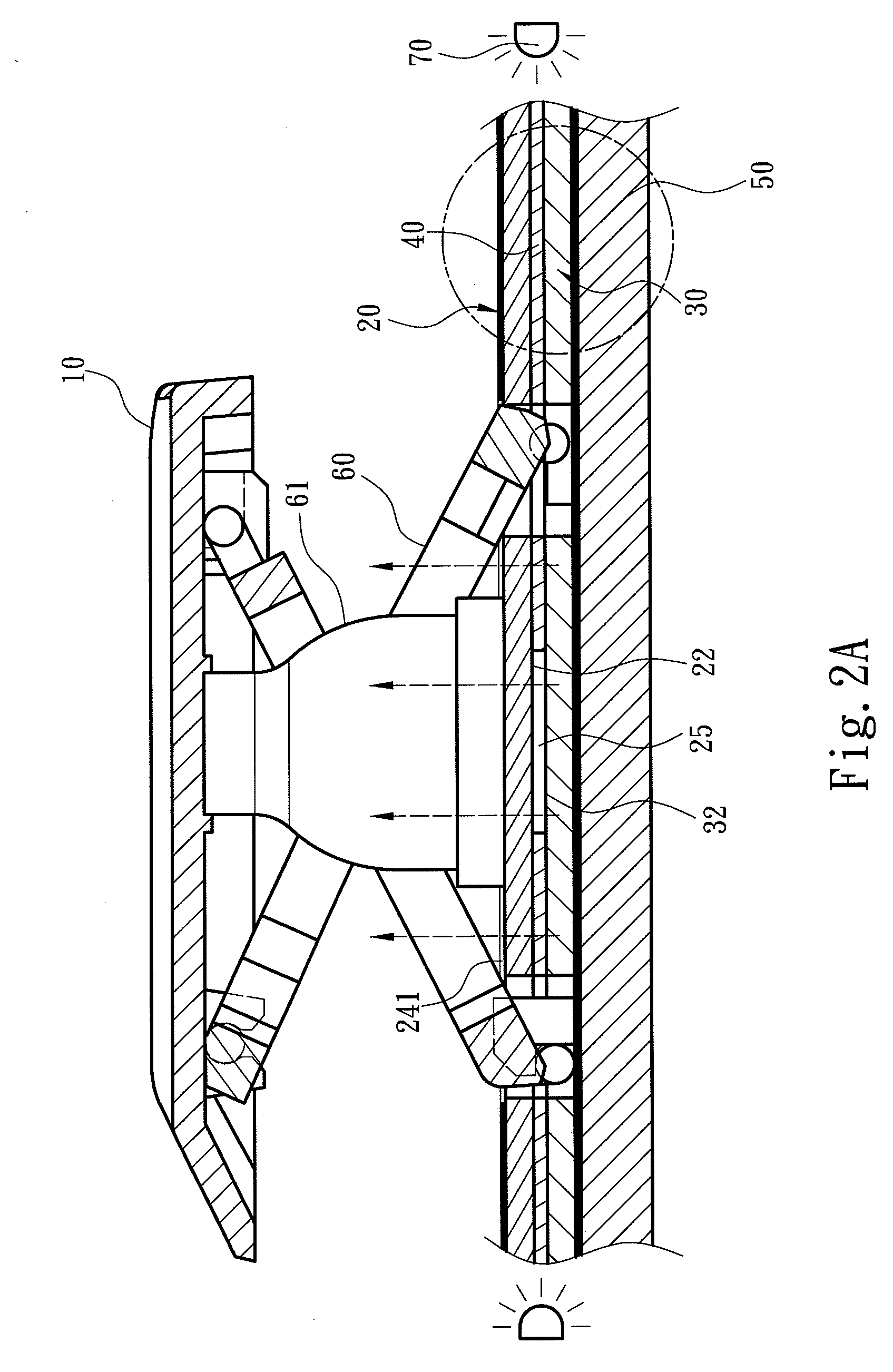
[0015]Please refer to FIGS. 1 and 2A for the thin illuminated keyboard of the invention. It comprises a keycap 10, an upper light guide plate 20, a lower light guide plate 30 and a partition plate 40 located between the upper light guide plate 20 and lower light guide plate 30. The upper light guide plate 20 and lower light guide plate 30 have respectively a first light guide layer 21 and a second light guide layer 31 opposing each other. The first light guide layer 21, second light guide layer 31 and partition plate 40 can be made of light guide material such as poly(methyl methacrylate), polycarbonate or the like.

[0016]As shown in FIG. 1, the first light guide layer 21 and second light guide layer 31 have respectively a first circuit layer 22 and a second circuit layer 32 laid on the opposing surfaces thereof. The first circuit layer 22 and second circuit layer 32 are interposed by at least one circuit switch 25 corresponding to the keycap 10. The partition plate 40 has an opening...

third embodiment

[0021]FIG. 4 illustrates a third embodiment in which the upper light guide plate 20 includes a top plate 26 and a lateral portion 27 that can be formed by bending the upper light guide plate 20 to a right angle. The upper light guide plate 20 and lateral portion 27 form a holding space to hold the partition plate 40 and lower light guide plate 30. In this embodiment, the lateral portion 27 is formed at one side of the top plate 26. In practice, the lateral portion 27 can be formed at two sides of the top plate 26 or at the edges thereof. Through the first mask layer 24 formed on the lateral portion 27, the light scattered from the lateral sides of the upper light guide plate 20, lower light guide plate 30 and partition plate 40 is blocked and reflected by the first reflection layer 23.

[0022]As a conclusion, the thin illuminated keyboard of the invention mainly utilizes the first and second light guide layers covered by the first and second reflection layers to reflect the light betw...


PUM


Abstract

A thin illuminated keyboard comprises at least one keycap, an upper light guide plate and a lower light guide plate. The upper and lower light guide plates have respectively a first light guide layer and a second light guide layer opposing each other. The first and second light guide layers have respectively a first circuit layer and a second circuit layer laid on the opposing surfaces thereof. The first and second light guide layers also have respectively a first mask layer and a second reflection layer on the sides opposite to the first and second circuit layers to form an optical passage therebetween. The first mask layer has at least one light penetration zone receiving light from the optical passage. The light is transmitted and confined in the optical passage between the first and second light guide layers, and condensed to project to the keycap through the light penetration zone.

Description

FIELD OF THE INVENTION[0001]The present invention relates to a thin illuminated keyboard and particularly to a thin illuminated keyboard to condense and project light to keycaps to improve illumination.BACKGROUND OF THE INVENTION[0002]In order to meet varying users' requirements, illuminated keyboards that integrate lighting modules to generate illumination have been developed and introduced on the market to attract consumers and provide an extra feature to increase their purchase motivation. While emphasizing the illuminated function, many producers also endeavor to reduce total thickness of the keyboard module so that it can be widely adapted to notebook computers or desktop computers highlighting thin and light design.[0003]Conventional thin illuminated keyboards, for instance, R.O.C. patent No. M352718 discloses an illuminated keyboard which comprises a key set unit, a thin film circuit board and a lighting unit. The thin film circuit board includes a thin film bottom layer, a t...

Claims


Application Information

Patent Timeline
Patent Type & Authority Applications(United States)
IPC IPC(8): H01H13/76
CPCH01H13/83H01H2219/062H01H2219/06H01H2219/044
Inventor HWA, CHIN-HSIU
Owner ZIPPY TECH
Why Eureka
Try Eureka