Seesaw-type wave power generating device

a power generation device and wave technology, applied in the direction of electric generator control, renewable energy generation, greenhouse gas reduction, etc., can solve the problems of uneasy maintenance, telescopic pump and support, telescopic pump unable to generate air stably, etc., to achieve easy maintenance, simple structure, and easy implementation

Inactive Publication Date: 2011-07-14
CHEN SHIH HSIUNG
View PDF15 Cites 18 Cited by
  • Summary
  • Abstract
  • Description
  • Claims
  • Application Information

AI Technical Summary

Benefits of technology

[0011]In comparison with prior art, the seesaw-type wave power generating device according to the present invention has a plurality of buoys floating on the water, so that the maintenance thereof is easy. Since the seesaw-type wave power generating device according to the present invention bobs due to water waves, the liquid moves back and forth between the first buoy and the second buoy. When the liquid moves from one buoy to the other buoy, the moving liquid drives the impeller generator to rotate, thereby generating electricity. Thus, the present invention has a simple structure for easy implementation. Further, check valves may be provided in the intersecting portions between the buoys and the connecting pipes to open or close in an alternate manner, thereby making the impeller generator to rotate continuously for generating electricity. Thus, the present invention really demonstrates an improved practicability.

Problems solved by technology

However, the telescopic pump and the support may suffer damage easily due to the lash of ocean waves, which makes the telescopic pump unable to generate air stably.
On the other hand, since the wave power generating device is disposed in the ocean, the maintenance is uneasy.
As a result, such a small dynamic energy of compressed air merely generates a limited amount of electricity and its power-generating efficiency is insufficient and uneconomical.

Method used


Image

  • Seesaw-type wave power generating device
  • Seesaw-type wave power generating device
  • Seesaw-type wave power generating device

Examples


Embodiment Construction

[0023]The detailed description and technical contents of the present invention will become apparent with the following detailed description accompanied with related drawings. It is noteworthy to point out that the drawings is provided for the illustration purpose only, but not intended for limiting the scope of the present invention.

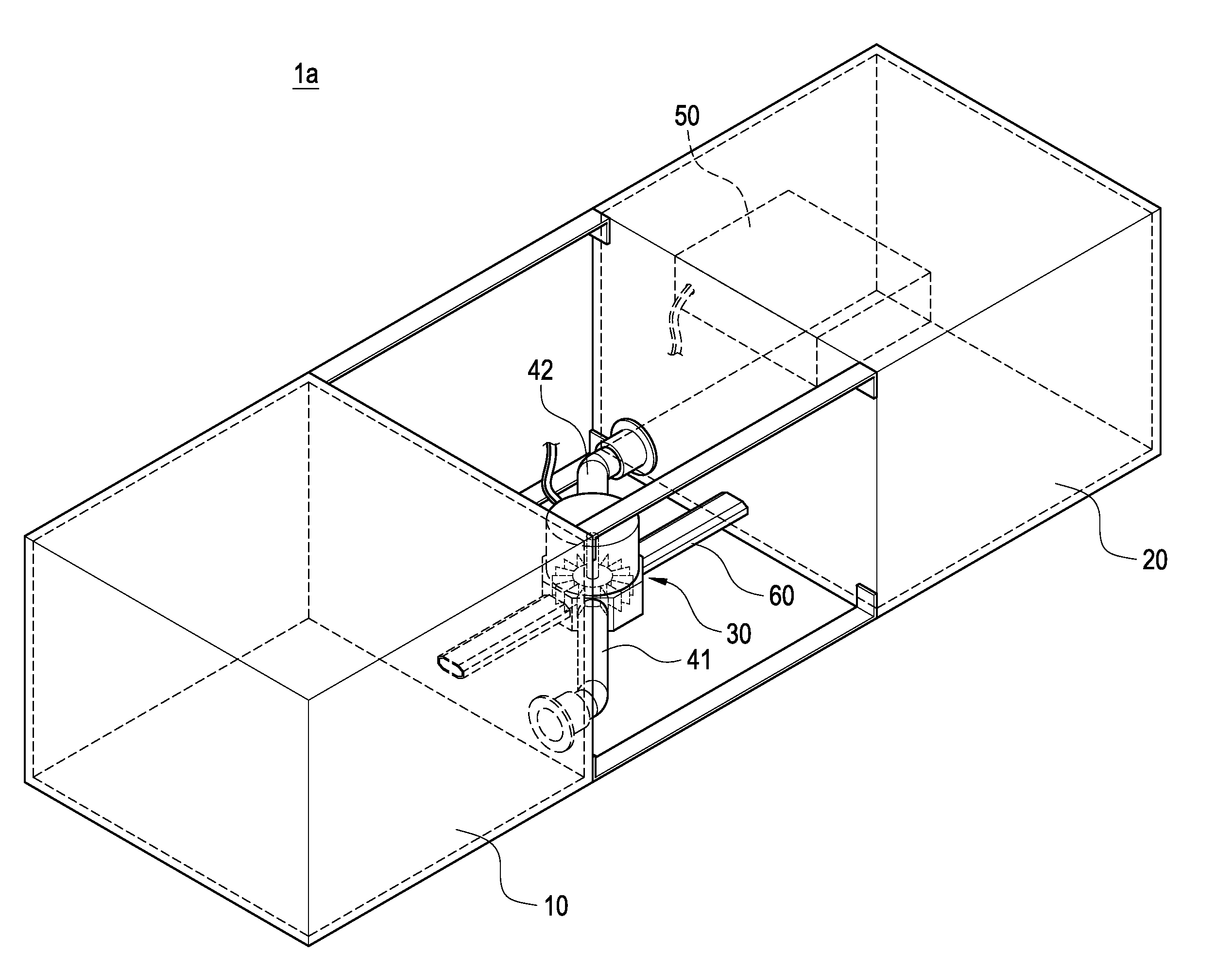
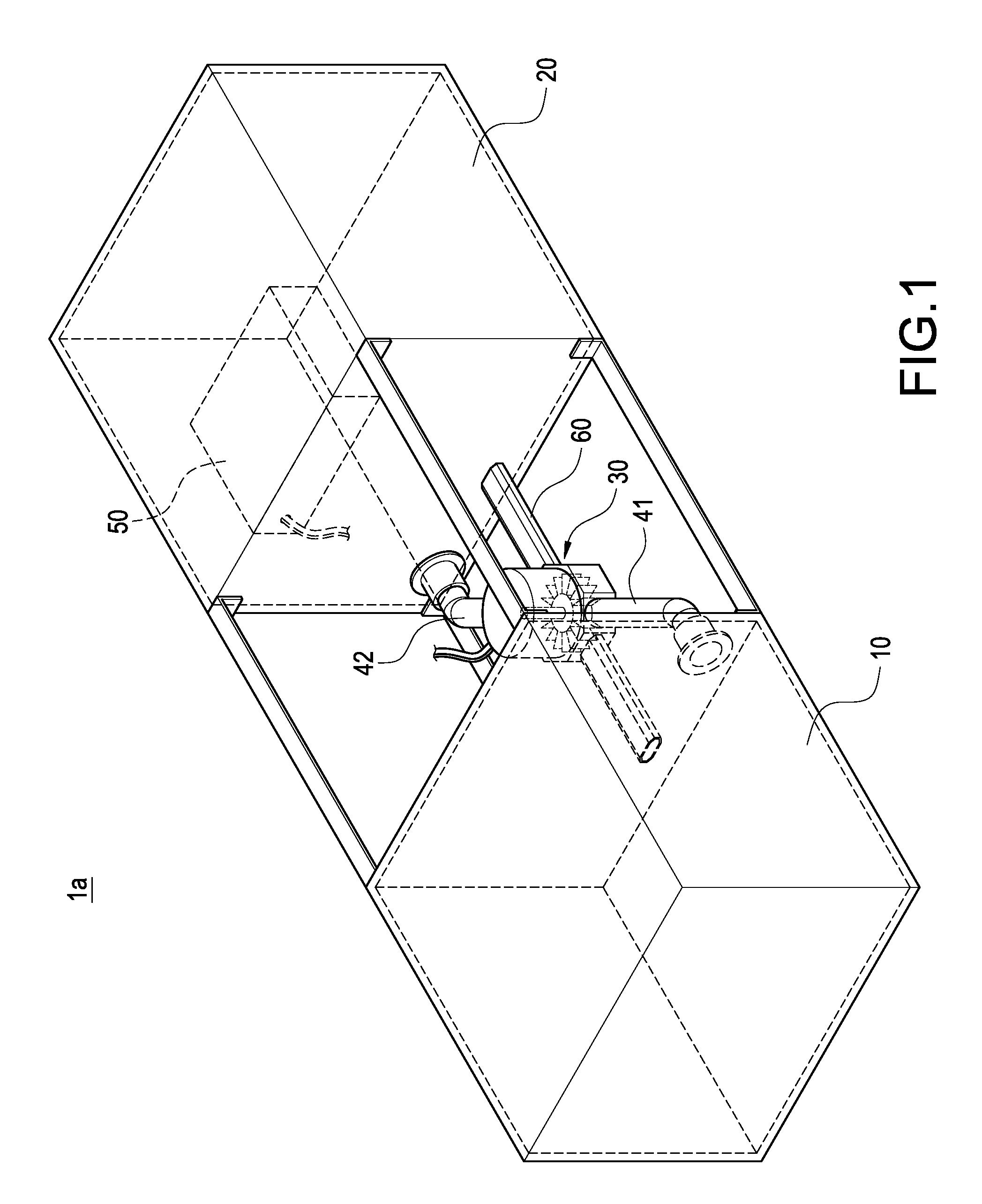
[0024]Please refer to FIG. 1, which is a schematic view showing the external appearance of the seesaw-type wave power generating device according to the first embodiment of the present invention. The seesaw-type wave power generating device 1a of the present invention includes a first buoy 10, a second buoy 20, an impeller generator 30, a first connecting pipe 41 and a second connecting pipe 42.

[0025]Each of the first buoy 10 and the second buoy 20 has a hollow casing. The second buoy 20 is disposed on one side of the first buoy 10 at an interval. The impeller generator 30 is disposed between the first buoy 10 and the second buoy 20.

[0026]The first conne...


PUM


Abstract

A seesaw-type wave power generating device (1) includes: a first buoy (10); a second buoy (20) disposed on one side of the first buoy (10); an impeller generator (30) disposed between the first buoy (10) and the second buoy (20); a first connecting pipe (42) having both ends communicated with the first buoy (10) and the impeller generator (30); and a second connecting pipe (42) having both ends communicated with the second buoy (20) and the impeller generator (30). A liquid (2) is filled in the first buoy (10) and the second buoy (20). The first buoy (10) and the second buoy (20) bob on the water and water waves (4) causes the liquid (2) to flow back and forth between the first connecting pipe (41) and the second connecting pipe (42), thereby driving the impeller generator (30) to generate electricity. The present invention is easy for implementation and maintenance.

Description

BACKGROUND OF THE INVENTION[0001]1. Field of the Invention[0002]The present invention relates to a water power generating device, in particular to a wave power generating device.[0003]2. Description of Prior Art[0004]Since the amount of petroleum stored all over the world is limited and the global warming is getting serious, many nations in the world have already paid attention to develop new power-generating technology by using renewable energies and inexhaustible natural resources (such as solar power, wind power and ocean power) because they have lower impact on the earth environment.[0005]Wave power generation is a power-generating technology for generating electricity by using ocean wave power, which has low impact on the earth environment and it is inexpensive and safe. According to the estimation made by resource experts, 0.1 percentage of the dynamic energy of the ocean wave can generate five times the amount of electricity necessary for the whole world. Thus, it is very wor...

Claims


Application Information

Patent Timeline
Patent Type & Authority Applications(United States)
IPC IPC(8): F03B13/20
CPCF03B7/00F03B13/148Y02E10/38Y02E10/223F03B13/16F03B13/22Y02E10/20Y02E10/30F03B13/14F03B13/20F05B2240/93
Inventor CHEN, SHIH-HSIUNGWENG, CHENG-SHI
Owner CHEN SHIH HSIUNG
Why Eureka
Try Eureka