Method and apparatus for controlling the position of an electric motor

a technology of electric motors and position determination, which is applied in the direction of motor/generator/converter stoppers, dynamo-electric converter control, machines/engines, etc., can solve the problems of inaccuracy in positioning workpieces and inaccurate counting of next drive pulses provided to drive motors, and achieve inaccuracy in position determination

a technology of electric motors and position determination, which is applied in the direction of motor/generator/converter stoppers, dynamo-electric converter control, machines/engines, etc., can solve the problems of inaccuracy in positioning workpieces and inaccurate counting of next drive pulses provided to drive motors, and achieve inaccuracy in position determination

US20110169432A1Inactive Publication Date: 2011-07-14KELSEY HAYES CO

Image

  • Method and apparatus for controlling the position of an electric motor
  • Method and apparatus for controlling the position of an electric motor
  • Method and apparatus for controlling the position of an electric motor

Examples


Embodiment Construction

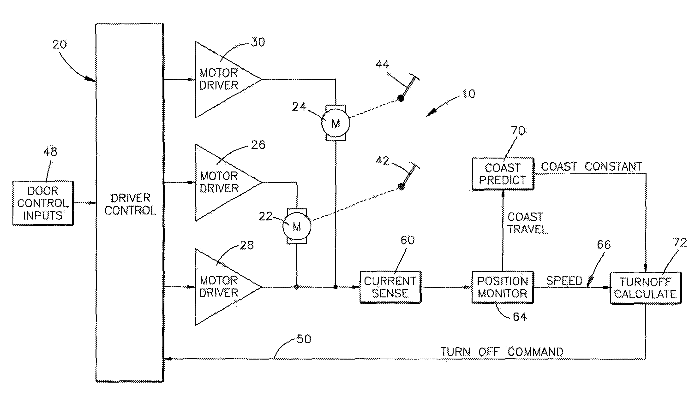
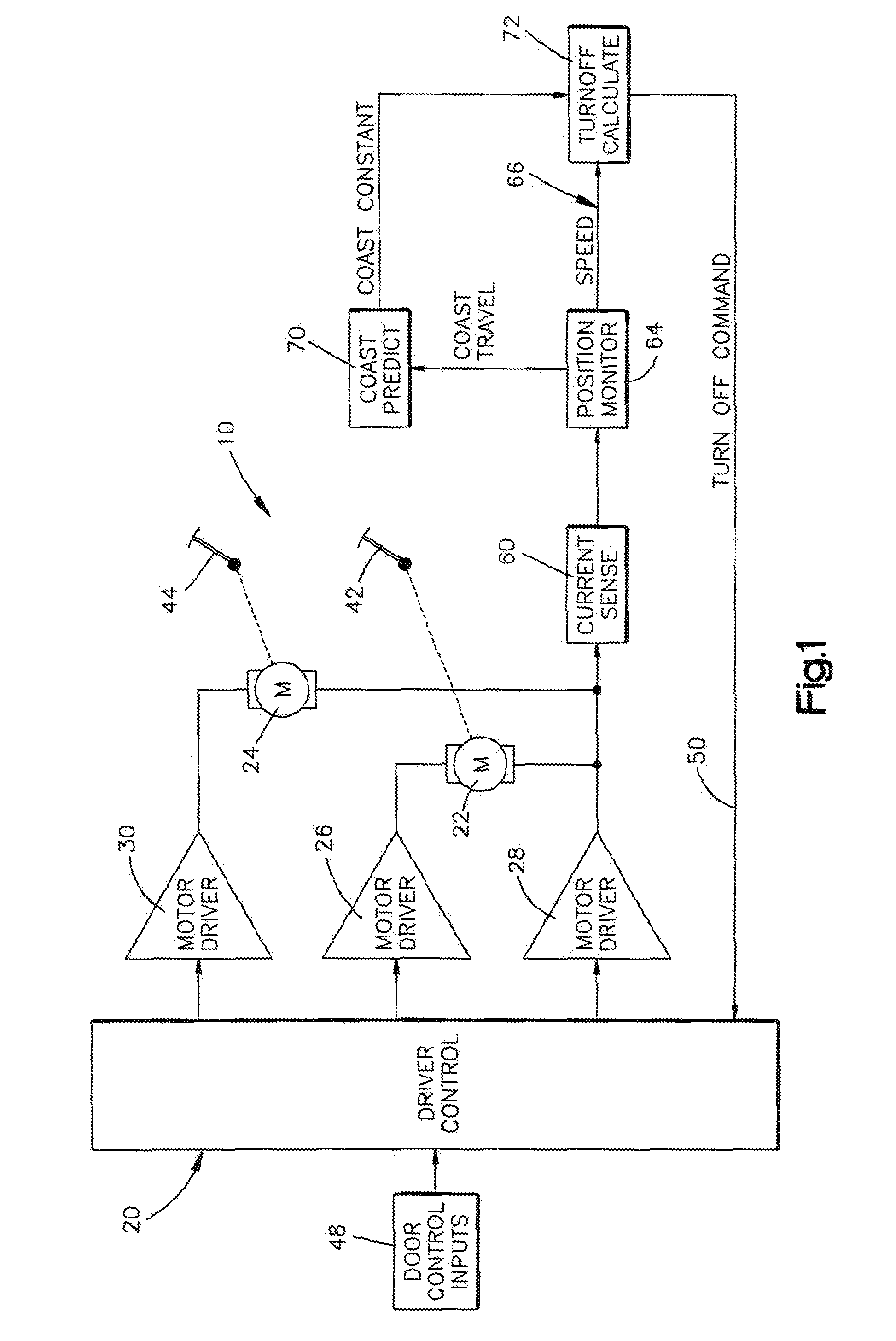
[0010]Referring to FIG. 1, a motor drive circuit 10, having a precision motor stop feature, in accordance with one example embodiment of the present invention, is shown. The motor drive circuit 10 includes a drive control 20 coupled to one or more motors 22, 24 through motor drive circuits 26, 28, 30. By way of example, the motors 22, 24 may be used in a vehicle climate control system to control the position of climate control doors 42, 44, respectively, that, in turn, control the air flow into the cabin of the vehicle. The motors 22, 24 can be dc brush-type motors. The armature of the dc motors are connected to actuator members (not shown) through associated gear mechanism (not shown) so that actuation of the motors 22, 24 causes an associated movement of the doors 42, 44, respectively.

[0011]The motor drivers 26, 28, 30 may take the form of application specific integrated circuits (“ASICs”) each including field effect transistors (“FETs”) that are associated with each dc motor that...


PUM


Abstract

A method is provided for controlling a position of an electric dc brush motor (22, 24) including the steps of supplying drive current (104) to drive the electric motor and calculating (70, 108) a coast constant for the motor. Current through the motor is monitored (80) and motor speed (66) is determined in response to monitored motor current. Electrical current to the motor is interrupted (50) in response to the calculated coast constant (70, 106) and motor speed when it is desired to stop the electric motor so that a brush of the motor will come to rest at a location on a commutator segment of the motor (22, 24).

Description

RELATED APPLICATION[0001]This application claims priority from U.S. Provisional Patent Application Ser. No. 61 / 097,367, filed Sep. 16, 2008, the subject matter of which is incorporated herein by reference in its entirety.FIELD OF THE INVENTION[0002]The present invention is directed to electric motors and is more particularly directed to a method and apparatus for controlling the position of an electric motor.BACKGROUND OF THE INVENTION[0003]Electric motors are often used to drive a work piece. When the motor is stopped, there is a chance that a contact brush of the motor will land very near the boundary between one of the motor's commutator segments. Typically, a count of drive pulse signals applied to the motor is used to determine the motor position and, in turn, the position of the work piece. If the motor contact brush is between commutator segments, the count of the next drive pulse provided to drive the motor may not be accurate in determining motor position. If a drive is ina...

Claims


Application Information

Patent Timeline
14 Jul 2011
Publication
US20110169432A1
IPC
H02P3/08; B60H1/24
CPC
H02P7/2805
Inventors
DEAN, JAMES J.