Fast start-up low-voltage bandgap reference voltage generator

a low-voltage bandgap reference voltage and fast startup technology, applied in the direction of electric variable regulation, process and machine control, instruments, etc., can solve the problems of error still occurring, error may occur, etc., and achieve the effect of fast start-up

Inactive Publication Date: 2011-07-14
RICHTEK TECH
View PDF12 Cites 27 Cited by
  • Summary
  • Abstract
  • Description
  • Claims
  • Application Information

AI Technical Summary

Benefits of technology

[0010]An object of the present invention is to provide a fast start-up low-voltage bandgap reference voltage generator.
[0011]According to the present invention, a fast start-up low-voltage bandgap reference voltage generator uses a first current generator having a self-bias circuit for providing a first current having a positive temperature coefficient, a second current generator for providing a second current having a negative temperature coefficient, a current summation circuit for generating a summed current equal to the sum of the first and second currents, and an output resistor for generating an output voltage independent of temperature according to the summed current. The self-bias circuit includes a

Problems solved by technology

In addition, the self-bias circuit of FIG. 1 needs two MOSFETs M1 and M2 to establish the current I1, and the self-bias circuit of FIG. 2 also needs two MOSFETs M1 and M2 to establish the current I5, so that error may be occurred if the MOSFETs M1 and M2 are not matched to each other.
Although this bandgap reference

Method used


Image

  • Fast start-up low-voltage bandgap reference voltage generator
  • Fast start-up low-voltage bandgap reference voltage generator
  • Fast start-up low-voltage bandgap reference voltage generator

Examples


first embodiment

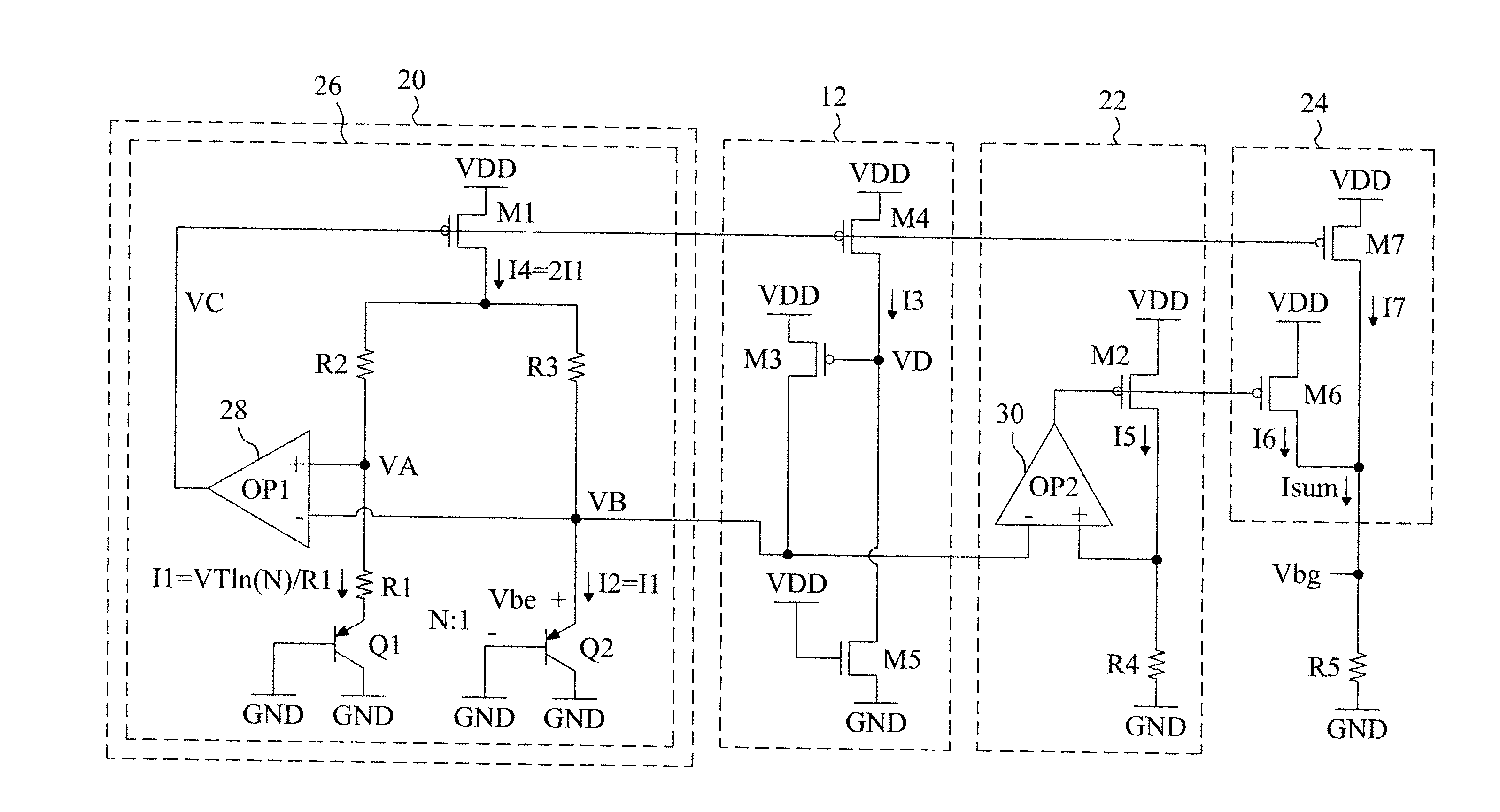
[0017]FIG. 3 is a circuit diagram of a first embodiment according to the present invention, in which two current generators 20 and 22, a current summation circuit 24 and an output resistor R5 are combined with the start-up circuit 12 of FIG. 1. The current generator 20 includes a self-bias circuit 26, in which a MOSFET M1 has an input terminal connected to a power supply terminal VDD, an operational amplifier 28 has an output terminal VC connected to a control terminal of the MOSFET M1, a BJT Q1 is configured as a diode, a resistor R1 is connected between a positive input terminal VA of the operational amplifier 28 and the BJT Q1, a resistor R2 is connected between an output terminal of the MOSFET M1 and the positive input terminal VA of the operational amplifier 28, a resistor R3 having a resistance equal to that of the resistor R2 is connected between the output terminal of the MOSFET M1 and a negative input terminal VB of the operational amplifier 28, and a BJT Q2 is configured a...

second embodiment

[0020]The embodiment of FIG. 3 is slightly modified to be a second embodiment as shown in FIG. 4. In the self-bias circuit 26, the MOSFET M1 is an NMOSFET, the positive input terminal of the operational amplifier 28 is VB, and the negative input terminal is VA. In the current generator 22, the MOSFET M2 is an NMOSFET, and the operational amplifier 30 has a positive input terminal connected to the positive input terminal VB of the operational amplifier 28, and a negative input terminal connected to the output terminal of the MOSFET M2. In the start-up circuit 12, the MOSFET M4 is an NMOSFET, a MOSFET M8 is added between the output terminal of the NMOSFET M4 and the control terminal VD of the MOSFET M3, and an operational amplifier 32 is added and has a positive input terminal connected to the output terminal of the NMOSFET M1, a negative input terminal connected to the output terminal of the NMOSFET M4, and an output terminal connected to the control terminal of the MOSFET M8. In the...


PUM


Abstract

A fast start-up low-voltage bandgap reference voltage generator uses two current generators to provide a first current having a positive temperature coefficient and a second current having a negative temperature coefficient, respectively, and a resistor to generate a temperature independent output voltage according to the sum of the first and second currents. The current generator for providing the first current has a self-bias circuit which uses a single MOSFET to establish the first current, and thereby avoids error caused by mismatched MOSFETs.

Description

FIELD OF THE INVENTION[0001]The present invention is related generally to a bandgap reference voltage generator and, more particularly, to a fast start-up low-voltage bandgap reference voltage generator.BACKGROUND OF THE INVENTION[0002]As shown in FIG. 1, a typical bandgap reference voltage generator has a self-bias circuit 10 and a start-up circuit 12 for starting up the bandgap reference voltage generator. In the self-bias circuit 10, two MOSFETs M1 and M2 have control terminals connected to each other and to an output terminal VC of an operational amplifier 14, a resistor R1 and a bipolar junction transistor (BJT) Q1 that is configured as a diode are serially connected between a positive input terminal VA of the operational amplifier 14 and a ground terminal GND, a BJT Q2 that is configured as a diode is connected between a negative input terminal VB of the operational amplifier 14 and the ground terminal GND, a resistor R2 and the MOSFET M1 are serially connected between a power...

Claims


Application Information

Patent Timeline
IPC IPC(8): G05F3/20
CPCG05F3/30
Inventor CHU, KWAN-JENKUNG, NIEN-HUIWANG, HSUAN-KAI
Owner RICHTEK TECH
Why Eureka
Try Eureka