Device and method for controlling bit density of magnetic card

a bit density and magnetic card technology, applied in the field of recording, can solve the problems of inability to adjust the bit density of the magnetic card, the control cost is correspondingly increased, and the standard bit density fails to meet the demand of an industrial user, so as to increase the hardware cost, easily expand, and change flexibly the bit density

Active Publication Date: 2011-07-14
SHANDONG NEW BEIYANG INFORMATION TECH CO LTD
View PDF0 Cites 0 Cited by
  • Summary
  • Abstract
  • Description
  • Claims
  • Application Information

AI Technical Summary

Benefits of technology

[0031]Compared with the prior art, the present invention has the advantages of changing flexibly the bit density of the magnetic card according to requirements and satisfying the demand that two or more tracks use different bit densities without increasing the hardware cost. Specifically speaking, a stepper motor is used as a power source with the rotation speed and the stop position thereof depending upon the frequency and the pulse number of the driving pulse signal, such that the magnetic card or the recording magnetic head is controlled to move as required for ensuring the movement of the magnetic card or the recording magnetic head to synchronize with the driving pulse of the stepper motor. The frequency of the magnetic writing pulse signal and that of the driving pulse signal of the stepper motor are in a linear relationship. the driving pulse of the stepper motor can be converted into a magnetic writing pulse according to the requirement of the bit density so as to accomplish data recoding. The frequency of the driving pulse signal of the stepper motor is adjusted or the frequency of the driving pulse signal of the stepper motor is divided or multiplied to obtain a corresponding magnetic writing pulse signal, to meet the requirements for the specific bit density. In particular, multiple magnetic writing pulse signals can be simultaneously obtained in the present invention, thereby it can be easily expanded into multiple bit density controlling channels so as to satisfy the requirement that two or more tracks use different bit densities; moreover, the photoelectric encoder is omitted and it is unnecessary to add the hardware, which are beneficial for cost reduction.

Problems solved by technology

With the expansion of the application fields of the magnetic card, the standard bit densities fail to satisfy the demand of an industrial user.
However, said control device has certain drawbacks, i.e., once the photoelectric encoder 5 is selected, the maximum number of an outputted pulse signal is unchanged, such that the bit density of the magnetic card can not be adjusted.
In addition, the greater the bit density value is, the higher the precision of the photoelectric encoder is, thus the control cost is increased correspondingly.
In addition, said device can only control the bit density of one track, which does not meet the requirement that two or more tracks use different bit densities, thereby its application is limited.

Method used


Image

  • Device and method for controlling bit density of magnetic card
  • Device and method for controlling bit density of magnetic card
  • Device and method for controlling bit density of magnetic card

Examples


first embodiment

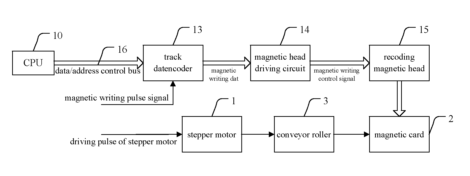
[0045]Referring to FIG. 2, the figure is a schematic diagram of a device for controlling a bit density of a magnetic card according to the present invention. Said device for controlling the bit density of the magnetic recording apparatus comprises: a stepper motor 1, a conveyor roller 3, a CPU 10, a track data encoder 13, a magnetic head driving circuit 14, a recording magnetic head 15, a data / address / control bus 16, etc., wherein:

[0046]the conveyor roller 3 is configured to transfer correspondingly power outputted by a prime mover (the stepper motor 1 in this embodiment) to a magnetic card 2, viz. to drive the magnetic card 2 to move relative to the recording magnetic head 15;

[0047]a CPU 10 is configured to send related information of magnetic recording via the data / address / control bus 16, the related information including data information, address information, and control information;

[0048]a track data encoder 13 is configured to receive a magnetic writing pulse signal and the rel...

second embodiment

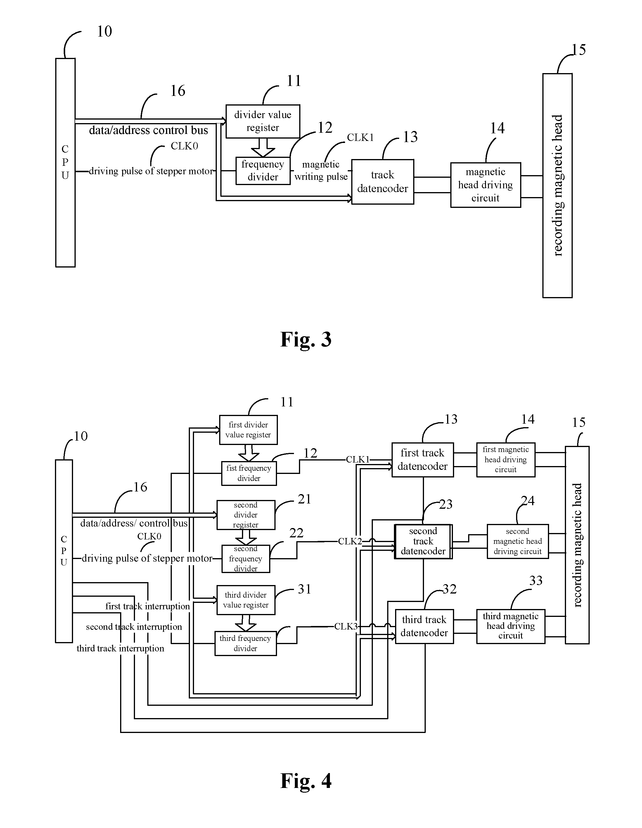
[0056]Referring to FIG. 3, said figure is a schematic diagram of a device for controlling a bit density of a magnetic card according to the present invention. The device for controlling the bit density of the magnetic card in this embodiment comprises a stepper motor (not shown in FIG. 3), a conveyor roller (not shown in FIG. 3), a CPU 10, a divider value register 11, a frequency divider 12, a track data encoder 13, a magnetic head driving circuit 14, a magnetic head 15, a data / address / control bus 16, etc, with the operation process thereof is as follows.

[0057]The CPU 10 transmits the data information, address information, or control information via the data / address / control bus 16 to the divider value register 11 and the track data encoder 13. The divider value register 11 is configured to receive the divider value sent by the CPU and said divider value is determined depending upon a sit density value. The frequency divider 12 is configured to receive the divider value, to divide th...

fifth embodiment

[0074]Referring to FIG. 6, said figure is a schematic diagram of a device for controlling a bit density of a magnetic card according to the present invention. In this embodiment, the bit densities of the second track and third track are the same, thereby the second divider value register 21 and the second frequency divider 22 are shared. Likewise, a multi-way selection switch 17 is provided for assigning a pulse CLKA outputted by the first frequency divider 12 to the first track data encoder 13 in the first channel to form a first magnetic writing pulse CLK1, and assigning a magnetic writing pulse CLKB outputted by the second frequency divider 22 simultaneously to the second track data encoder 23 and the third track data encoder 33 in the second and third channels to form a corresponding second magnetic writing pulse CLK2 and third magnetic writing pulse CLK3. In this way, two sets of a divider value register and a frequency divider are provided, and it can realize controlling the b...


PUM

PropertyMeasurementUnit
densityaaaaaaaaaa
poweraaaaaaaaaa
frequencyaaaaaaaaaa

Abstract

A device and a method for controlling a bit density of a magnetic card (2) are provided. Said control device comprises a stepper motor (1) providing power to drive the magnetic card (2) or a recording magnetic head (15), a transmission mechanism transferring power to the magnetic card (2) or the recording magnetic head (15), a CPU (10) sending magnetic recording information, a track data encoder (13) receiving a magnetic writing pulse signal (CLK1) and generating magnetic writing data in synchronization with the magnetic writing pulse signal (CLK1), and a magnetic head driving circuit (14) outputting a magnetic writing control signal based on the magnetic writing data. The frequency of the magnetic writing pulse signal (CLK1) and the frequency of a driving pulse signal (CLK0) of the stepper motor are in a linear relationship. Said control method is a method for controlling a bit density.

Description

[0001]The present application claims the priority of Chinese Patent No. 200810211688.2 filed with the Chinese Patent Office on Sep. 18, 2008, entitled “Device and Method for Controlling Bit Density of Magnetic Card”, and the contents thereof in entirety are herein incorporated by reference.FIELD OF THE INVENTION[0002]The present invention relates to the field of recording by excitation or demagnetization of a recording medium, specifically speaking, to a device and a method for controlling a bit density of a magnetic card.BACKGROUND OF THE INVENTION[0003]A magnetic card is a kind of a magnetic recording media card which is made of a film base of a certain material and a particulate magnetic material coated uniformly on the film base, and has moisture-resistant and wear-resistant characteristics, certain flexibility, portability and a relatively stable and reliable usefulness. Depending on the materials of the film base, the magnetic card can be classified into two types, a plastic m...

Claims


Application Information

Patent Timeline
Patent Type & Authority Applications(United States)
IPC IPC(8): G11B25/04
CPCG06K1/125
Inventor XU, ZHIGANGHU, GUANGDONGLIU, BINGQINGOU, MINGANGXIE, ZHENHU
Owner SHANDONG NEW BEIYANG INFORMATION TECH CO LTD
Why Eureka
Try Eureka