Method of data delivery across a network fabric in a router or ethernet bridge

a network fabric and router technology, applied in the direction of digital transmission, data switching by path configuration, electrical equipment, etc., can solve the problems of limited number of ports which can be supported within an individual bridge, high cost, and high cost so as to improve routing and data delivery, the effect of high port count of ethernet bridges and routers

Active Publication Date: 2011-07-14
CRAY UK
View PDF31 Cites 18 Cited by
  • Summary
  • Abstract
  • Description
  • Claims
  • Application Information

AI Technical Summary

Benefits of technology

[0040]Thus, with the present invention a method for Ethernet encapsulation is provided which enables improved routing and data delivery across a network fabric, without change to the underlying Ethernet protocol structures or contents. This provides, amongst other things, the mechanism to guarantee the order of Ethernet data delivered across such a network that includes multiple paths between source and destination endpoints, completely removing the possibility of mis-ordering or duplication being propagated by the network, enabling the construction of very high port count Ethernet Bridges and Routers.

Problems solved by technology

Although described as scalable, this and other Ethernet switches consisting of many separate low port count modules that are dependent upon a common bus, are fundamentally unsuited to networks involving very large numbers of processors such as storage centres and server farms.
The number of ports which can be supported within an individual bridge is limited by the bus capacity of these architectures.
As the density, capacity and data rates of individual connections increases these common bus architectures limit the construction of large Ethernet networks, bus bandwidth quickly being exceeded by a relatively small number of high performance connections.

Method used


Image

  • Method of data delivery across a network fabric in a router or ethernet bridge
  • Method of data delivery across a network fabric in a router or ethernet bridge
  • Method of data delivery across a network fabric in a router or ethernet bridge

Examples


Embodiment Construction

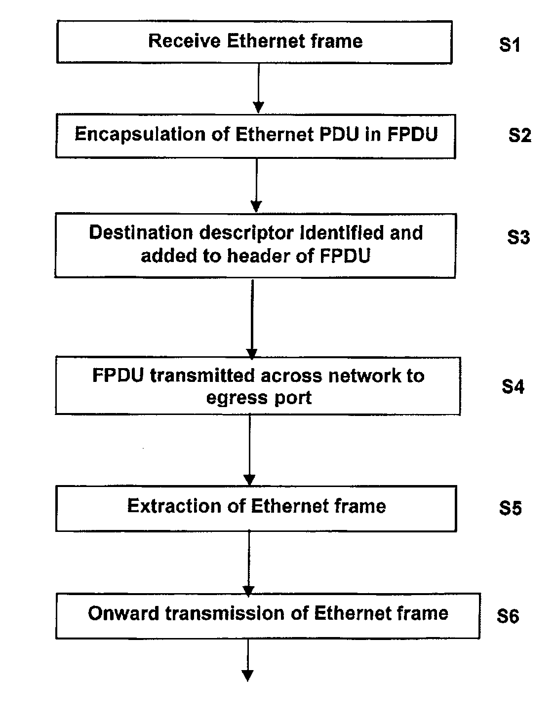
[0048]The Ethernet bridge or router described below introduces an additional protocol layer, referred to herein as an ‘Encapsulation Layer’, that appears between the Physical Layer and the Data Link Layer of the standard OSI model which can encapsulate both Network Layer and Data Link Layer PDUs.

[0049]Complete encapsulation in a PDU unique to the present invention, which is referred to herein as a ‘Fabric Protocol Data Unit’ (FPDU), avoids the necessity of modifying the underlying PDU frame headers or trailers, and thus removes the overhead of recalculating the cyclic redundancy check (CRC) or other derived information based upon the contents of the frame. A FPDU is used in implementation of the data transmission, acknowledgement and flow-control mechanisms and can be further utilised to provide many other attractive features important to large high performance, scalable Ethernet networks.

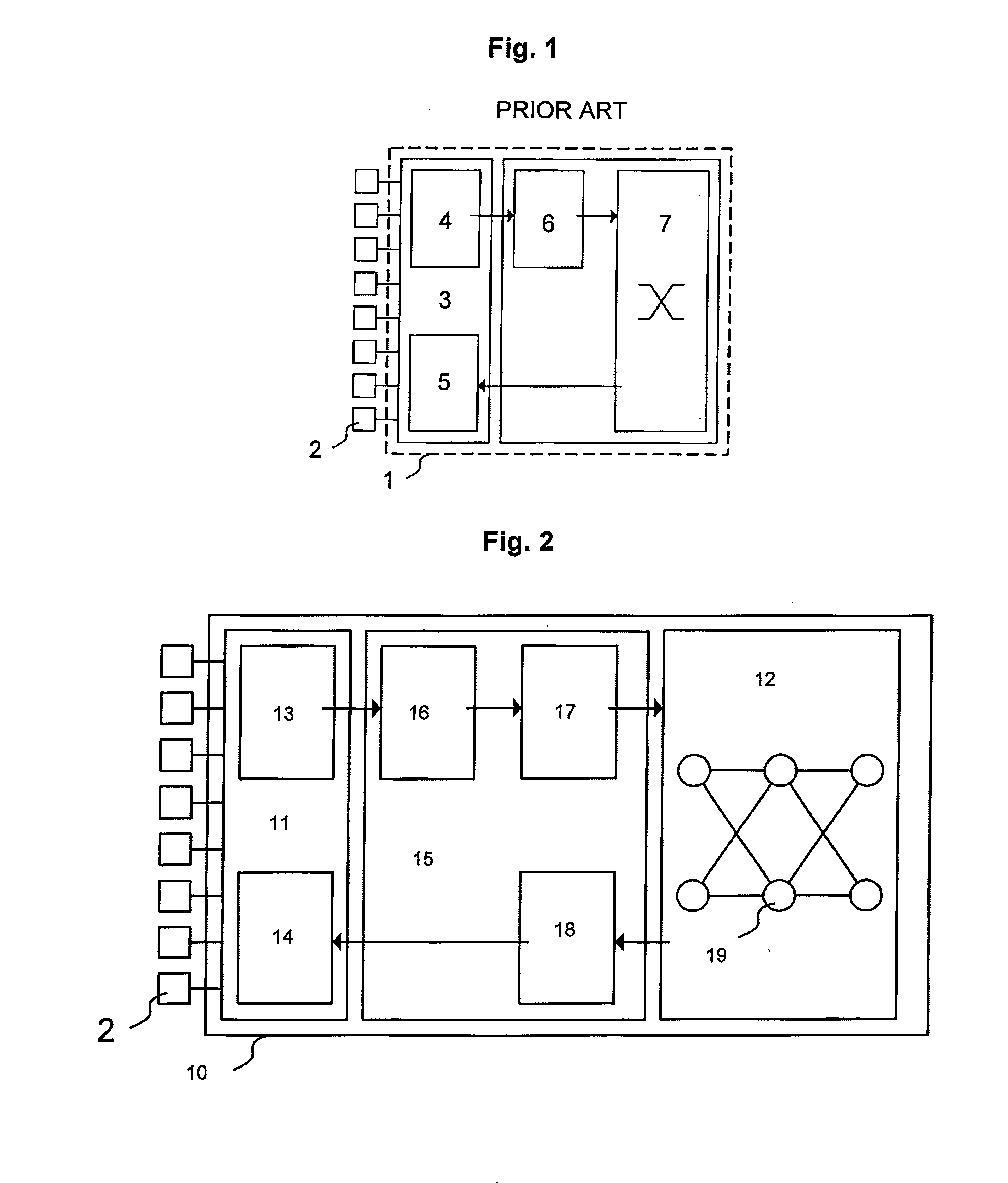
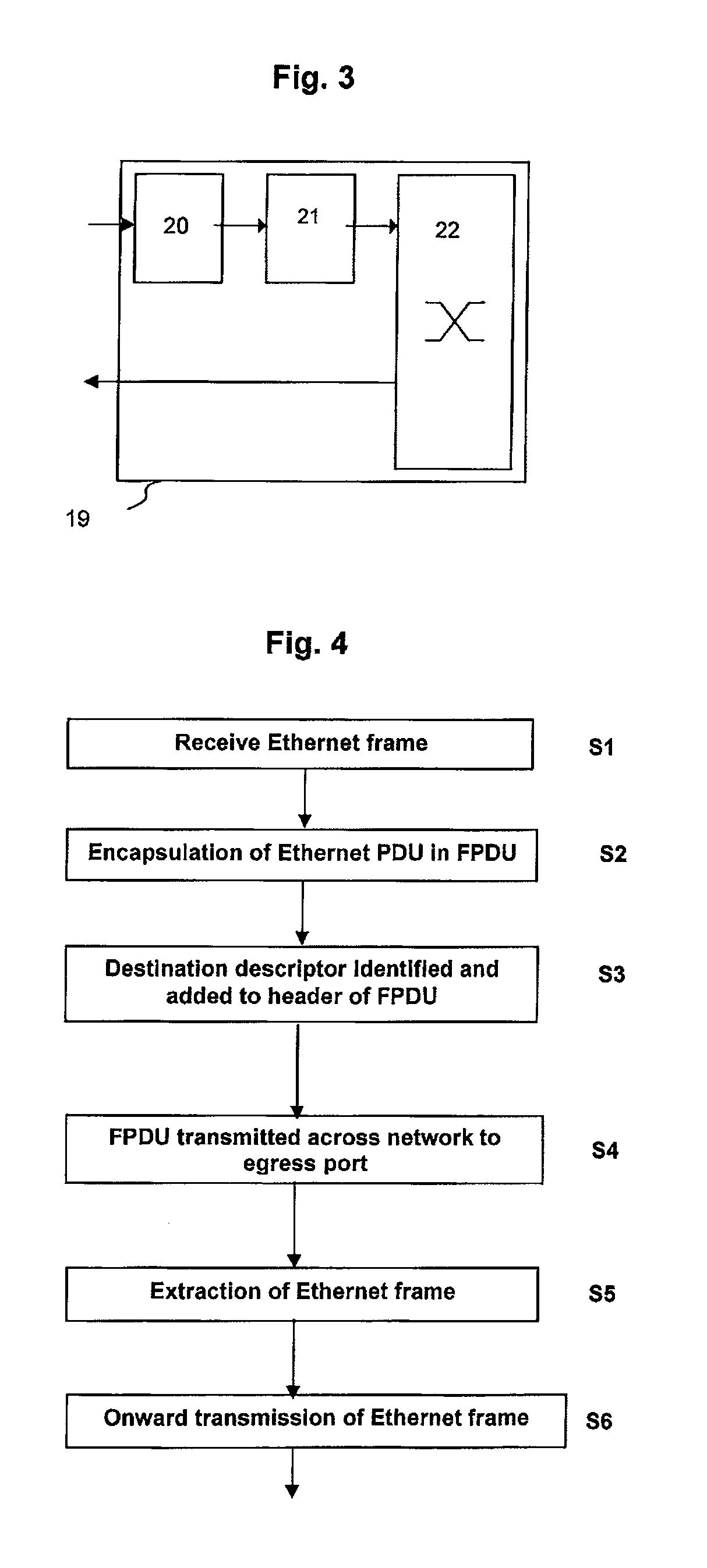
[0050]An Ethernet bridge or router 10 is illustrated in FIG. 2 which may be connected to a plur...


PUM


Abstract

The invention provides an Ethernet bridge or router comprising a network fabric adapted to provide interconnectivity to a plurality of Ethernet ports, each of the Ethernet ports being adapted to receive and/or transmit Ethernet frames, and wherein the Ethernet bridge or router further comprises an encapsulator connected to receive Ethernet Protocol Data Units from the Ethernet ports, wherein the encapsulator is operable to generate a Fabric Protocol Data Unit from a received Ethernet Protocol Data Unit, the Fabric Protocol Data Unit comprising a header portion, and a payload portion which comprises the Ethernet Protocol Data Unit concerned, and wherein the encapsulator is operable to transform Ethernet destination address information from the Ethernet Protocol Data Unit into a routing definition for the network fabric, and to include this routing definition in the header portion of the Fabric Protocol Data Unit. Also provided is a method of data delivery across a network.

Description

BACKGROUNDTechnical Field of the Invention[0001]The present invention generally relates to an Ethernet bridge or router and to a method of data delivery across a network suitable for use in, but not limited to, multi-processor networks such as storage networks, data centres and high performance computing. In particular, the present invention is concerned with an Ethernet bridge or router which is adapted for the distribution of standard IEEE 802 data frames or data frames meeting future Ethernet standards.Protocol Layers[0002]Conceptually, an Ethernet network is decomposed into a number of virtual layers in order to separate functionality. The most common and formally standardised model used is the Open Systems Interconnect (OSI) reference model. A useful article which described in detail the OSI reference model is “OSI Reference Model—The ISO Model of Architecture for Open Systems Interconnection” by Hubert Zimmermann, IEEE Transactions on Communications, Vol. COM-28, No. 4, April ...

Claims


Application Information

Patent Timeline
Patent Type & Authority Applications(United States)
IPC IPC(8): H04L12/56H04L49/111
CPCH04L49/3009H04L2212/0025H04L49/351H04L2212/00H04L12/4633
Inventor BEECROFT, JONHEWSON, DAVID CHARLESFORD, ANTHONY MICHAELHOMEWOOD, MARK OWEN
Owner CRAY UK
Why Eureka
Try Eureka