Expandable Spacer and Method For Use Thereof

a spacer and expandable technology, applied in the field of expandable implants, can solve the problems of disc pathologies severe, disc height and possible annulus fibrosis delamination, and disc function impairment, and achieve the effect of facilitating arthrodesis or fusion

Active Publication Date: 2011-07-14
GLOBUS MEDICAL INC
View PDF11 Cites 184 Cited by
  • Summary
  • Abstract
  • Description
  • Claims
  • Application Information

AI Technical Summary

Benefits of technology

[0012]An expandable implant having an adjustable height for insertion between two adjacent bony structures or two adjacent joint surfaces is disclosed. In one variation, the implant may include at least one gear, at least one threaded shaft, and a base or collar. The parts (gear, shaft, base) can be any size capable of functioning to expand the implant. Insertion of the implant facilitates arthrodesis or fusion of the bony structures or joints. Although intended to be useful with any adjacent bony structures or joint surfaces in which fusion is desired, the implant is particularly applicable to the spine, wherein it is inserted into the intervertebral space remaining after removal of damaged disc material.

Problems solved by technology

Many factors can adversely alter the composition and structure of the intevertebral disc, such as normal physiological aging, mechanical injury / trauma, and / or disease, resulting in impairment or loss of disc function.
Therefore, in normal aging the disc progressively dehydrates, resulting in a decrease in disc height and possible de-lamination of the annulus fibrosus.
Regardless of the cause, many of these disc pathologies become severe enough to require surgical intervention
While the discectomy eliminates the problems associated with the damaged disc, it creates a void in the intervertebral space that, if left empty, can de-stabilize and possibly collapse the vertebrae, negatively affecting the whole vertebral column.
Although this basic technique is still in use today, bone grafts alone are slow to fuse and may not be anatomically correct even if fusion is achieved.
Furthermore, such bone grafts are often not strong enough to maintain long-term stability of the spine.
Although this type of system initially offers strength, the hardware can loosen over time decreasing this strength.
Despite the enormous progress in spinal therapy, chronic back pain remains a perplexing problem and the number of patients with back problems continues to rise.

Method used


Image

  • Expandable Spacer and Method For Use Thereof
  • Expandable Spacer and Method For Use Thereof
  • Expandable Spacer and Method For Use Thereof

Examples


Embodiment Construction

[0061]For the purpose of promoting an understanding of the principles of the invention, reference will now be made to embodiments illustrated herein and specific language will be used to describe the same. It will nevertheless be understood that no limitation of the scope of the invention is thereby intended. Any alterations and further modification in the described implants, methods, and any further application of the principles of the invention as described herein, are contemplated as would normally occur to one skilled in the art to which the invention relates. The implants described herein are not limited to the specific embodiments.

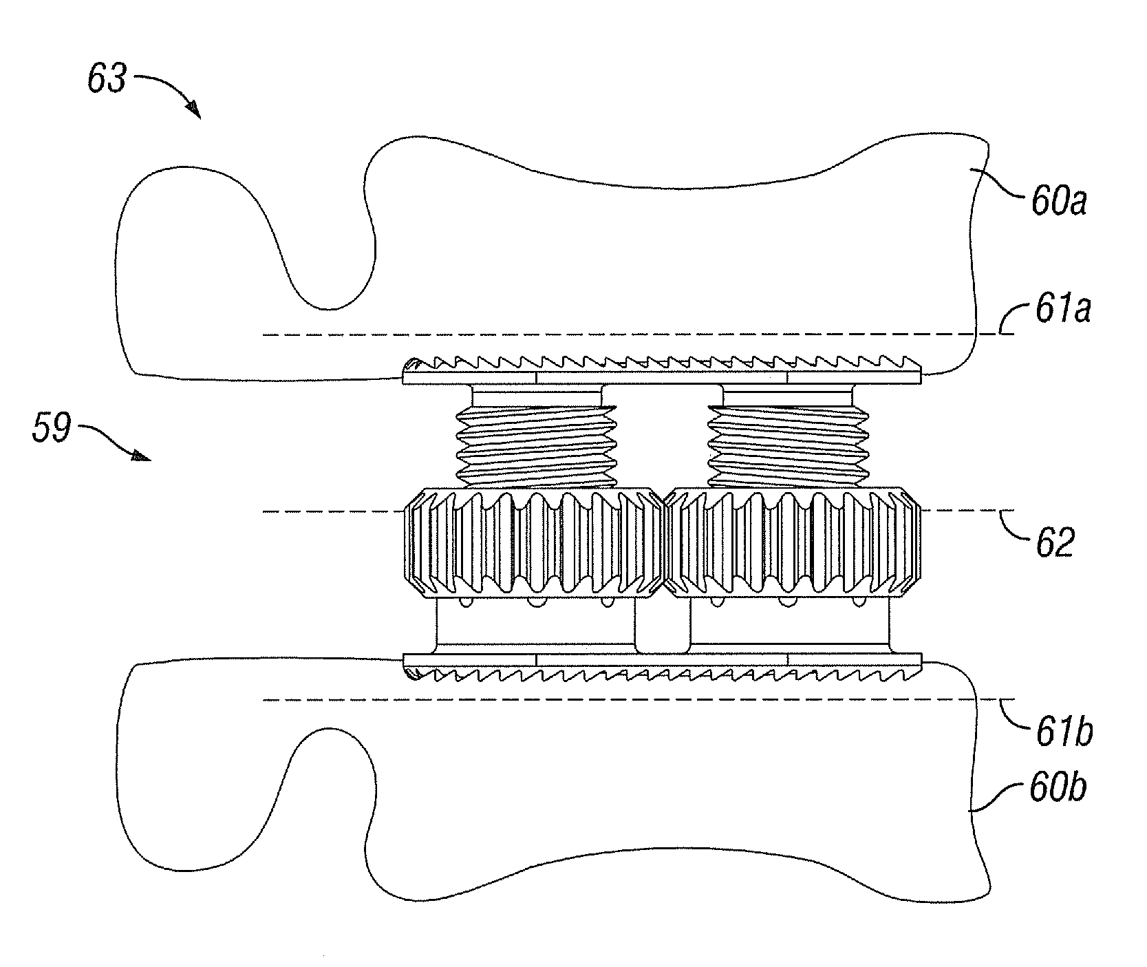
[0062]In general, the invention provides an expandable implant having an adjustable height. The implant is inserted between two adjacent bony surfaces to facilitate fusion of the bony surfaces. Although intended to be useful with any adjacent bony surface in which fusion is desired, the implant is advantageously applied to insertion between two adjac...


PUM


Abstract

An expandable implant is disclosed having an adjustable height for insertion between two adjacent bony structures or joint surfaces, for example between two adjacent spinal vertebrae. The implant includes at least one gear associated with at least one threaded shaft. Rotation of the gear engages the threaded shaft to expand the implant. The implant can be inserted in a collapsed configuration and expanded in situ. The invention also provides methods for using the implant to facilitate arthrodesis or fusion of adjacent joint surfaces or spinal vertebrae.

Description

FIELD OF THE INVENTION[0001]The invention generally relates to spacers for use in orthopedic treatments, particularly to implants for insertion between two adjacent bony structures or two adjacent joint surfaces, and most particularly, to an expandable implant for insertion into the void remaining in the intervertebral space after removal of damaged disc material.BACKGROUND[0002]The vertebral or spinal column (spine, backbone) is a flexible assembly of vertebrae stacked on top of each other extending from the skull to the pelvic bone which acts to support the axial skeleton and to protect the spinal cord and nerves. The vertebrae are anatomically organized into four generalized body regions identified as cervical, thoracic, lumbar, and sacral; the cervical region including the top of the spine beginning in the skull, the thoracic region spanning the torso, the lumbar region spanning the lower back, and the sacral region including the base of the spine ending with connection to the p...

Claims


Application Information

Patent Timeline
Patent Type & Authority Applications(United States)
IPC IPC(8): A61B17/88A61F2/28A61F2/44
CPCA61F2/0095A61F2310/00179A61F2/442A61F2/4455A61F2/4465A61F2/4611A61F2002/2817A61F2002/2835A61F2002/30133A61F2002/302A61F2002/30354A61F2002/30357A61F2002/30362A61F2002/30405A61F2002/3041A61F2002/30411A61F2002/30415A61F2002/30448A61F2002/30451A61F2002/305A61F2002/30523A61F2002/3055A61F2002/30553A61F2002/30579A61F2002/30586A61F2002/30588A61F2002/30601A61F2002/30616A61F2002/30785A61F2002/30841A61F2002/30843A61F2002/30858A61F2002/30859A61F2002/30957A61F2002/3096A61F2002/3097A61F2002/30976A61F2002/4475A61F2002/448A61F2210/0014A61F2310/00017A61F2310/00023A61F2310/00029A61F2310/00071A61F2/38A61F2002/30593A61F2002/30604A61F2002/30622
Inventor GLERUM, CHAD
Owner GLOBUS MEDICAL INC
Why Eureka
Try Eureka