Anchor System for Composite Panel

a composite panel and anchoring technology, applied in the direction of shock-proofing, walls, building components, etc., can solve the problems of requiring stronger anchors with concomitantly higher costs, deterioration of cavity wall insulation, wall construction, etc., and achieves high seismic protection, low weight, and high strength.

Active Publication Date: 2011-07-21
HOHMANN & BARNARD INC
View PDF27 Cites 68 Cited by
  • Summary
  • Abstract
  • Description
  • Claims
  • Application Information

AI Technical Summary

Benefits of technology

A veneer tie is interengaged with the anchoring system and set within the bed joints of the outer wythe. A reinforcement wire is interconnected with the veneer tie and disposed in the bed joint thereby providing a high degree of seismic protection. The veneer tie is either interengaged directly with the wall anchor or connected to the wall anchor through the use of a connection bar. The connection bar is capable of connection with a plurality of adjustable veneer ties that are aligned with the bed joints.
The present anchoring system for composite panels has varied applications and provides a universal solution. One such application is for interengagement with Centria's composite panel system. Centria's panel systems provide a high strength, low weight, insulated backup wall. The panels are interconnected using a tongue and groove system located at the connection of the inner and outer facing sheets. The wall anchor fits within the juncture of adjacent panels, maintaining the strong interlock of the panels, without obstructing the juncture or the drainage system. A first embodiment anchor is pronged and inserted directly into the composite panel to minimally disrupt the insulative properties of the panel core while further securing the wall anchor to the backup wall and providing a gauge for positioning the anchor. The A second embodiment anchor is contoured to completely fit within the composite panel juncture. Sealant is applied within the juncture to provide further protection against water and water vapor.
It is a feature of the present invention that the composite panel backup wall eliminates the need for batt insulation, exterior gypsum board, and building wraps.
It is yet another feature of the present invention that the integral veneer anchors are labor-saving and reduce costs.

Problems solved by technology

In the past, different building specifications and locations resulted in various structural problems such thermal transfer from the inner to the outer wythe, pinpoint loading, high lateral forces related to high-wind and seismic forces and cavity wall insulation deterioration.
Another obstacle in cavity wall construction is compliance with the greater insulation requirements set forth in the Massachusetts Energy Code, the Energy Code Requirement, Chapter 13 (78 CMR, Seventh Edition; Boston, Mass.).
The larger cavities, with the associated thicker insulation, require stronger anchors with concomitantly higher costs.
The resulting building is sturdy and insulative, but not as aesthetically pleasing as brick veneer.
In the past, although composite panels would provide an efficient back-up wall for commercial brick veneer construction, the lack of a proper anchoring system restricted this practice.
None of the prior art provides an all-in-one backup solution using composite panels.

Method used


Image

  • Anchor System for Composite Panel
  • Anchor System for Composite Panel
  • Anchor System for Composite Panel

Examples


first embodiment

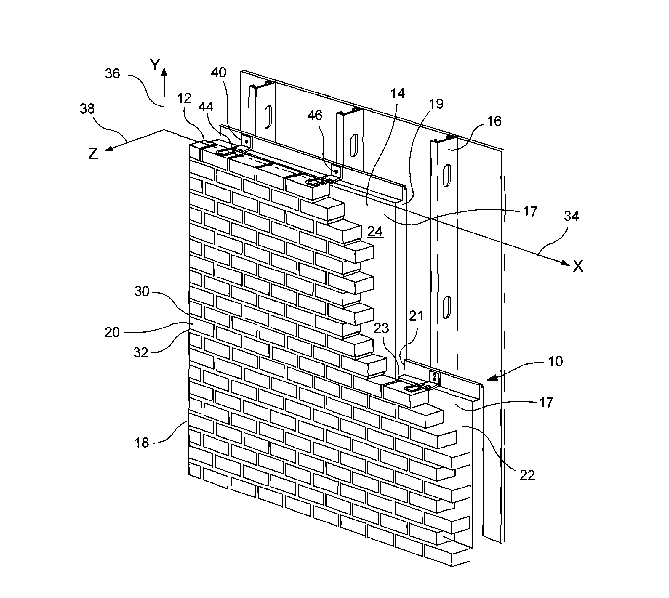
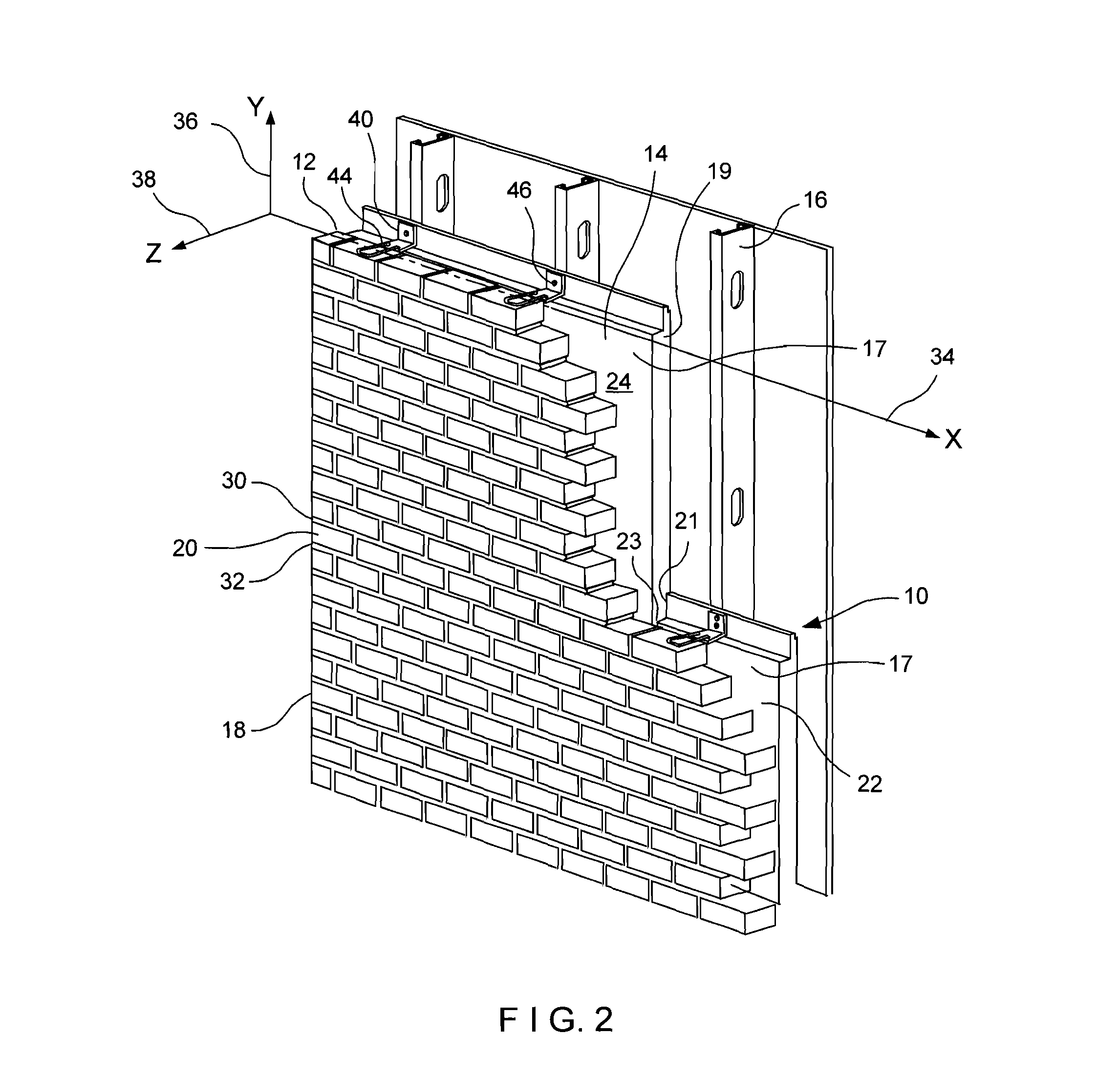
Referring now to FIGS. 2 through 5, the present invention shows the anchoring system for composite panels with a brick veneer outer wythe. The anchoring system for composite panels is referred to generally by the numeral 10. A cavity wall structure 12 is shown having an inner wythe or composite panel backup wall 14 supported on a structural framework or frame, including metal studs or vertical columns 16. The inner wythe 14 is assembled from interengaged individual panels 17 having adjacent panel ends 19, 21 forming a vertical juncture 23 and being connected along the lower and upper side edges 25, 26 to form a horizontal wall joint 28. The cavity wall 12 also includes an outer wythe or facing 18 of brick 20 construction. Between the inner wythe 14 and the outer wythe 18, a cavity 22 is formed.

Successive bed joints 30 and 32 are substantially planar and horizontally disposed and, in accord with building standards, are 0.375-inch (approx.) in height. Selective ones of bed joints 30 a...

second embodiment

The system includes the wall anchor 140 and a veneer tie 144. Although various veneer ties work in conjunction with the wall anchor 140, including the use of a connection bar and apertured veneer ties as described in the second embodiment set forth below (not shown) or a box or Byna-Tie threadedly mounted through the free end aperture (not shown), the veneer tie 144 shown is a wire formative pintle device manufactured by Hohman & Barnard, Inc., Hauppauge, N.Y. 11788. The veneer tie 144, is shown in FIG. 6 as being emplaced on the course of bricks 120 in preparation for embedment in the mortar of the bed joint 130. The veneer tie 144 is fixedly disposed in an x-z plane of the bed joint 130 and is constructed to adjustably position with the longitudinal axis substantially horizontal and to interengage with the wall anchor 140.

The veneer tie 144 is the same as the veneer tie shown in FIG. 5 and has an interengaging end 65 for disposition in said free end receptor portion 66 and an inse...


PUM


Abstract

Anchoring systems for use in cavity wall structures having an inner wythe constructed of interengaged composite panels and a veneer outer wythe are disclosed. The wall anchor is disposed within the juncture of the interengaged composite panels and fastened to the frame. The wall anchor maintains a strong interlock with the composite panels and backup wall, maintains insulation integrity and limits thermal transfer, without obstructing the juncture of the composite panels. The anchoring system interlocks with varied veneer ties, allowing vertical and horizontal adjustment for alignment with the bed joints. The anchoring system for composite panels provides an economical, high strength, low weight, insulated backup wall construction for interengagement with a veneer outer wythe.

Description

BACKGROUND OF THE INVENTION1. Field of the InventionThis invention relates to an anchoring system for cavity walls having an inner wythe of architectural panels. More particularly, the invention relates to a composite panel backup wall with a brick veneer.2. Description of the Prior ArtCavity wall construction backup walls take many forms, including dry wall, concrete masonry units, tilt-up poured concrete, and insulating concrete forms. Selection of the backup wall type is dependent upon location, type and size of construction and other varied considerations. Anchors specific to each type of backup wall construction are inserted into the backup wall to properly anchor the outer wythe or veneer in accordance with the building specifications and location.In the past, different building specifications and locations resulted in various structural problems such thermal transfer from the inner to the outer wythe, pinpoint loading, high lateral forces related to high-wind and seismic forc...

Claims


Application Information

Patent Timeline
Patent Type & Authority Applications(United States)
IPC IPC(8): E04C2/38E04B1/98E04B2/18E04B1/38
CPCE04B1/7616E04B1/4178
Inventor HOHMANN, JR., RONALD P.KLOS, MARK J.
Owner HOHMANN & BARNARD INC
Why Eureka
Try Eureka