Compressor and refrigerating machine

a compressor and refrigerating machine technology, applied in the field of compressors and refrigerating machines, can solve the problems of waste oil treatment upon the disposal of waste oil, complex configuration of the compressor, and harmful effects on the natural environment, so as to achieve the effect of simple configuration and easy disposal of lubricants

Active Publication Date: 2011-07-21
THE TOKYO ELECTRIC POWER CO INC +3
View PDF5 Cites 87 Cited by
  • Summary
  • Abstract
  • Description
  • Claims
  • Application Information

AI Technical Summary

Benefits of technology

[0009]An object of the present invention is to provide a compressor and a refrigerating machine which enable an easy disposal of a lubricant, are friendly to the natural environment, and have simple configurations.

Problems solved by technology

Therefore, there is a problem that the configuration of the compressor becomes complex.
This raises a concern that a harmful effect, such as a global warming, is given to the natural environment on its disposal.
This results in a problem that a troublesome waste oil treatment is required upon the disposal of the waste oil.Patent Document 1: Japanese Patent Application Publication No. 9-268988

Method used


Image

  • Compressor and refrigerating machine
  • Compressor and refrigerating machine
  • Compressor and refrigerating machine

Examples


first embodiment

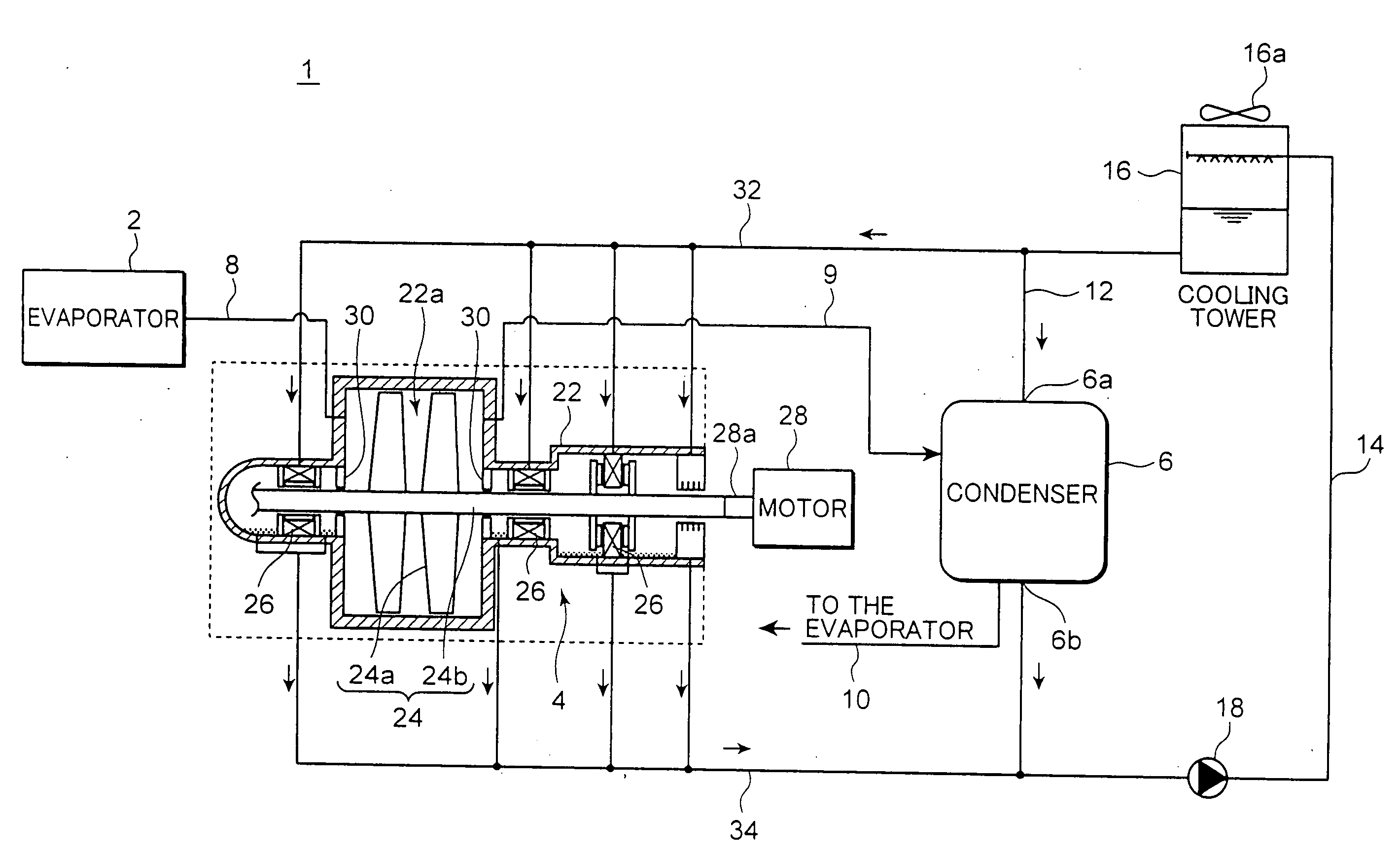
[0018]First, a whole configuration of the refrigerating machine 1 according to the first embodiment of the present invention is described with reference to FIG. 1.

[0019]The refrigerating machine 1 of the first embodiment is used, for example, in a cooling device, such as an air conditioner. Here, water is used as a refrigerant in the refrigerating machine 1.

[0020]Specifically, the refrigerant machine 1 according to the first embodiment includes an evaporator 2, a compressor 4, a condenser 6, a refrigerant introducing line 8, a refrigerant deriving line 9, a refrigerant supplying line 10, a coolant supplying line 12, a coolant returning line 14, a cooling tower 16, and a coolant pump 18. The refrigerant is circulated in a refrigerant cycle comprised of the evaporator 2, the compressor 4, the condenser 6, the refrigerant introducing line 8, the refrigerant deriving line 9, and the refrigerant supplying line 10. Meanwhile, coolant water is circulated in a coolant cycle comprised of the...

second embodiment

[0049]Next, the respective configurations of the compressor 4 and the refrigerating machine 41 according to the second embodiment are described referring to FIG. 3.

[0050]In the second embodiment, a condenser 46 is an indirect heat exchange type condenser, unlike the first embodiment. Thus, in the condenser 46, coolant water flowing through the coolant cycle does not contact to a refrigerant flowing through a refrigerant cycle. Further, the lubricant supplying line 32 connects the respective bearings 26 with a condensed water supplying line 50 through which condensed water is conveyed from the condenser 46 to the evaporator 2.

[0051]Specifically, the condenser 46 has a coolant introducing opening 46a and a coolant discharge opening 46b. The coolant introducing opening 46a of the condenser 46 is connected to the coolant supplying line 12, and the coolant discharge opening 46b of the condenser 46 is connected to the coolant returning line 14. Another end of the condensed water supplying...


PUM


Abstract

A compressor and a refrigerating machine which enable an easy disposal of a lubricant, are friendly to the natural environment, and have simple configurations, are provided.The compressor which is used in a refrigerating machine including an evaporator and a condenser and adapted for compressing refrigerant gas evaporated in the evaporator to convey the compressed refrigerant gas to the condenser, includes: a motor; a housing having a compression chamber inside; a rotary member which has a rotating shaft and is rotated by a driving force of the motor so as to compress water vapor serving as the refrigerant gas in the compression chamber; a bearing for supporting the rotating shaft of the rotary member in the housing; and a lubricant supplier for supplying water serving as a lubricant to the bearing.

Description

TECHNICAL FIELD[0001]The present invention relates to a compressor and a refrigerating machine.BACKGROUND ART[0002]Conventionally, there has been known a compressor which is used in a refrigerating machine and adapted for compressing refrigerant gas evaporated in an evaporator to convey the compressed refrigerant gas to a condenser (see, for example, Patent Document 1).[0003]FIG. 6 shows a configuration of the compressor disclosed in Patent Document 1. The compressor disclosed in Patent Document 1 is a two-step-type screw compressor operable to compress the refrigerant gas including a chlorofluorocarbon or the like, in two steps. The compressor includes a pair of a first step screw rotors 101, 102, and a pair of second step screw rotors 103, 104. The respective screw rotors 101 to 104 are accommodated in a casing 106.[0004]The first screw rotors 101 and 102 are so arranged as to engage with each other in a first compression chamber 106a in the casing 106. The second screw rotors 103...

Claims


Application Information

Patent Timeline
Patent Type & Authority Applications(United States)
IPC IPC(8): F28D5/00F16N25/00F25B39/04F04B17/00
CPCF04D25/06F04D29/057F04D29/063F16C33/109F25B9/002F25B31/002F25B2339/047F25B1/047F16C2362/52
Inventor IIZUKA, KOICHIROIDE, SATOSHIKANEMURA, TOSHIKATSUNAKAYAMA, YOSHIHIROTOSHIMA, MASATAKEOKADA, KAZUTOSUTO, KUNIHIKOKURASHIGE, KAZUTAKASAKURABA, ICHIROUHAYASHI, DAISUKEIKEUCHI, MASAKISHATO, SHINJIMOLLER, LARS BAYJENSEN, FINNAL-JANABI, ZIADRASMUSSEN, SVENDMADSBOLL, HANSSVARREGAARD-JENSEN, CHRISTIAN
Owner THE TOKYO ELECTRIC POWER CO INC
Why Eureka
Try Eureka