

Wireless power supplying system
a power supply system and wireless technology, applied in the direction of electric vehicle charging technology, inductance, transportation and packaging, etc., can solve the problems of reducing efficiency and difficult manual operation adjustment, and achieve the effect of high power supply efficiency
- Summary
- Abstract
- Description
- Claims
- Application Information
AI Technical Summary
Benefits of technology
Problems solved by technology
Method used
Image

Examples
first embodiment
1. First Embodiment
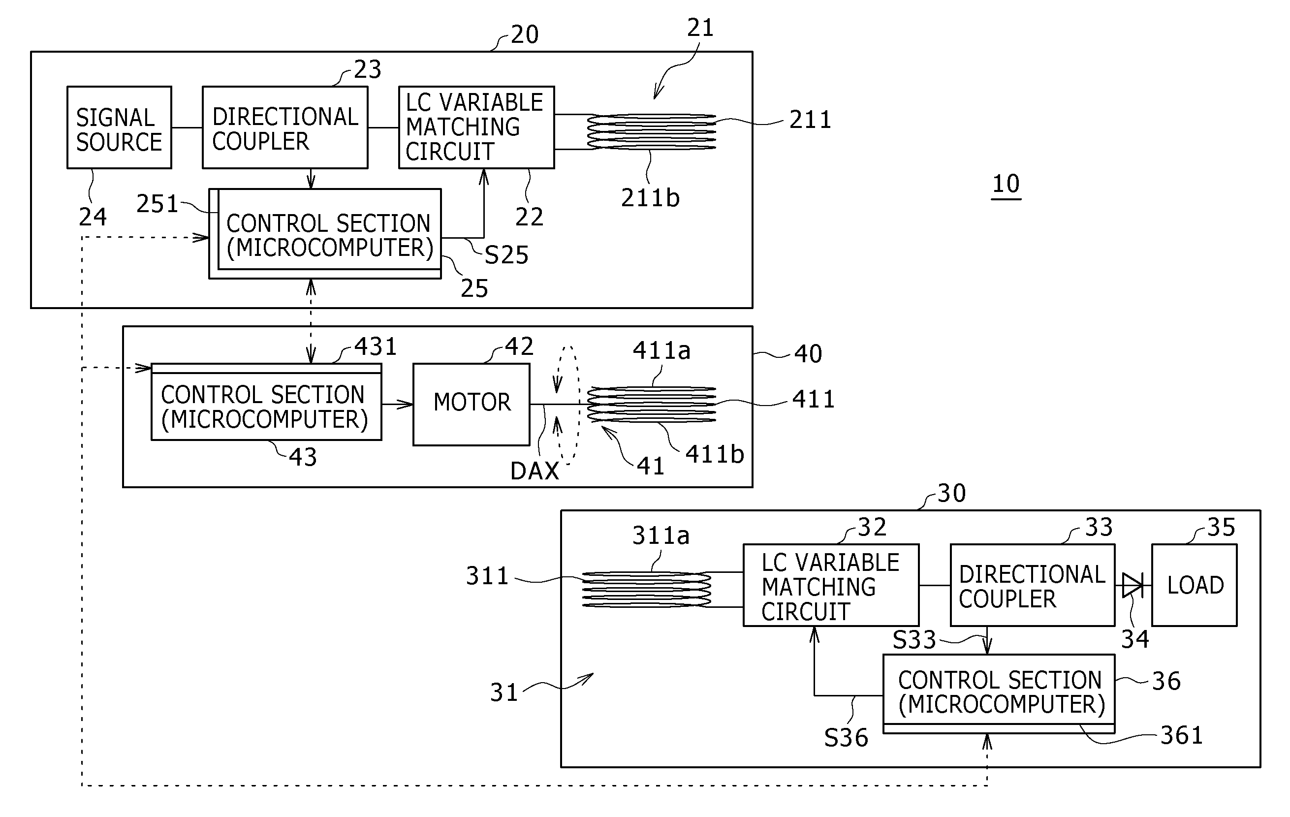
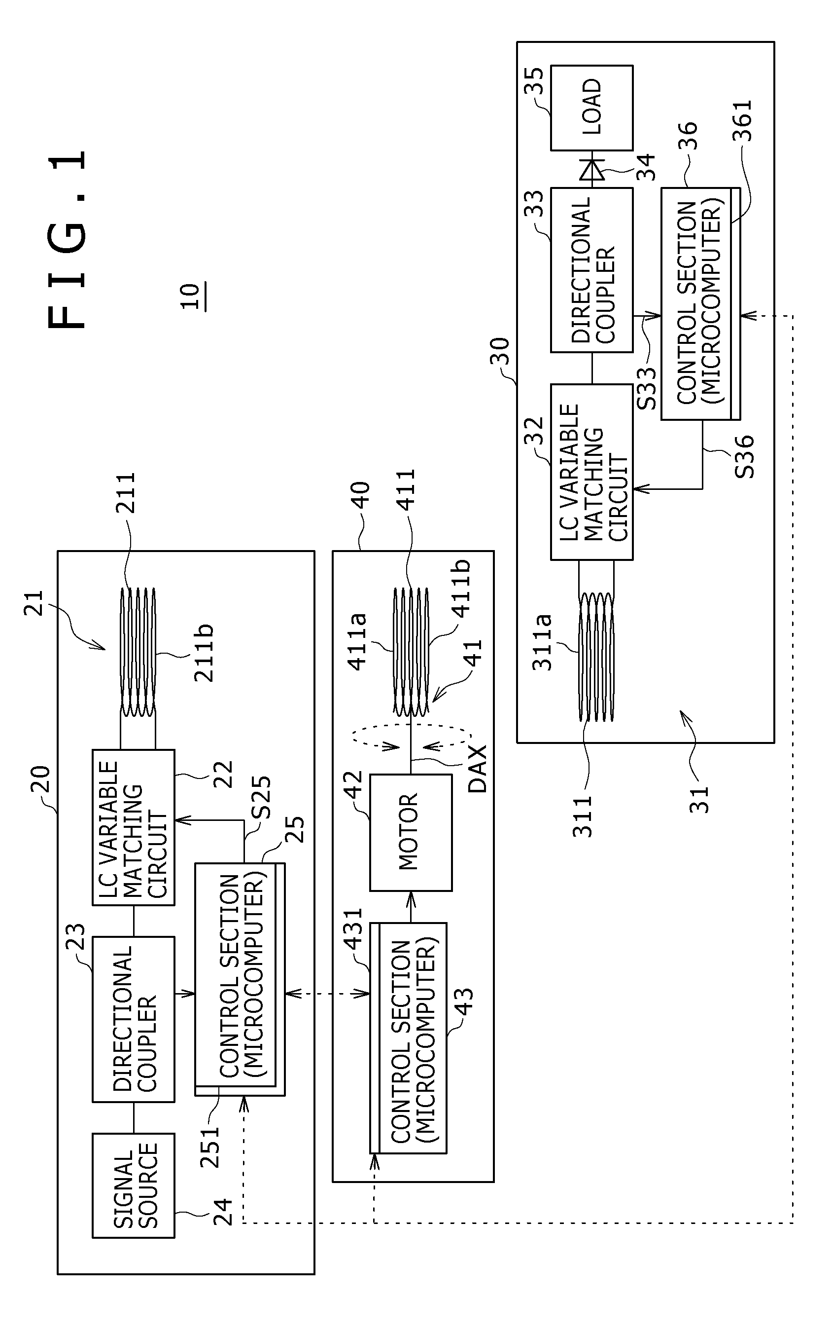
[0030]FIG. 1 shows an example of a configuration of a wireless power supplying system according to a first embodiment of the present invention.
[0031]The wireless power supplying system 10 includes a power transmission device 20, a power reception device 30 and a repeater device 40.
[0032]The power transmission device 20 includes a power transmission coil section 21, a variable matching circuit 22 serving as a first variable matching section, a directional coupler or excessively reflected power detection circuit 23 serving as a first detection section, a high-frequency signal generation circuit or signal source 24 and a control section 25 serving as a first control section.
[0033]The power transmission coil section 21 includes a resonance coil 211 serving as a first resonance device. While the resonance coil is also called as consonance coil, the term resonance coil is used in the present specification.
[0034]The resonance coil 211 is formed from an air-core coil, and...
second embodiment
2. Second Embodiment
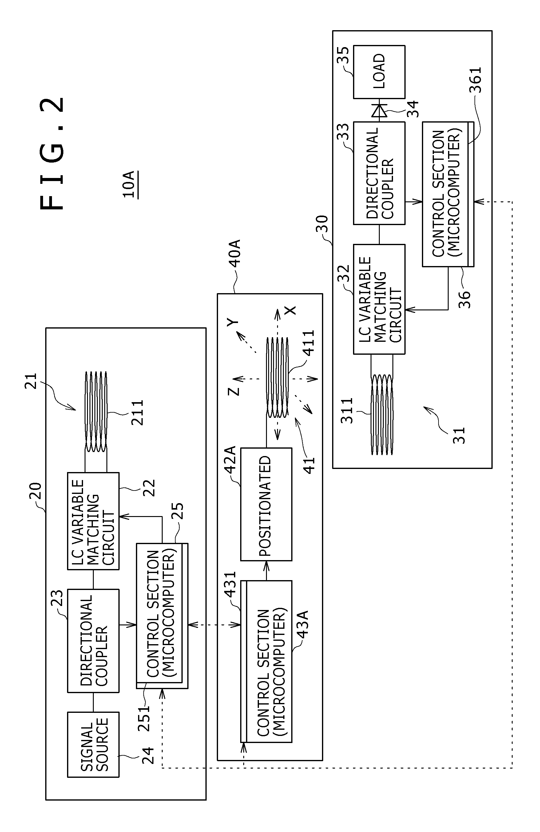
[0085]FIG. 2 shows an example of a configuration of a wireless power supplying system according to a second embodiment of the present invention.
[0086]Referring to FIG. 2, the wireless power supplying system 10A according to the present second embodiment is similar to but different from the wireless power supplying system 10 according to the first embodiment in that the alignment adjustment mechanism for the resonance coil 411 of the repeater device 40A incorporates a positioner 42A in place of the rotary motor.
[0087]The positioner 42A can move the resonance coil 411 in the X, Y and Z directions of a Cartesian coordinate system shown in FIG. 2 to adjust the position of the resonance coil 411.
[0088]The repeater device 40A exhibits a maximum efficiency when the resonance coil 411 which is a repeater element has a resonance frequency equal to those of the power transmission side resonance coil 211 and the power reception side resonance coil 311 and the resonance coil...
third embodiment
3. Third Embodiment
[0090]FIG. 3 shows an example of a configuration of a wireless power supplying system according to a third embodiment of the present invention.
[0091]Referring to FIG. 3, the wireless power supplying system 10B according to the present third embodiment is similar to but different from the wireless power supplying systems 10 and 10A according to the first and second embodiments in that the driving section of the repeater device 40B additionally has functions of the motor and the positioner in the first and second embodiments.
[0092]In particular, the repeater device 40 includes, as the driving section thereof, a motor and positioner 42B which has a function of the motor 42 for angular adjustment in the first embodiment and a function of the positioner 42A for position adjustment of the second embodiment.
[0093]With the present third embodiment, the position and the angle of the resonance coil 411 of the repeater device 40B are adjusted to supply power efficiently.
PUM
 Abstract
Description
Claims
Application Information