

Power converter
- Summary
- Abstract
- Description
- Claims
- Application Information
AI Technical Summary
Benefits of technology
Problems solved by technology
Method used
Image

Examples
Embodiment Construction
Exemplary embodiments of a power converter according to the present invention will be explained below in detail with reference to the accompanying drawings. The present invention is not limited to the embodiments.
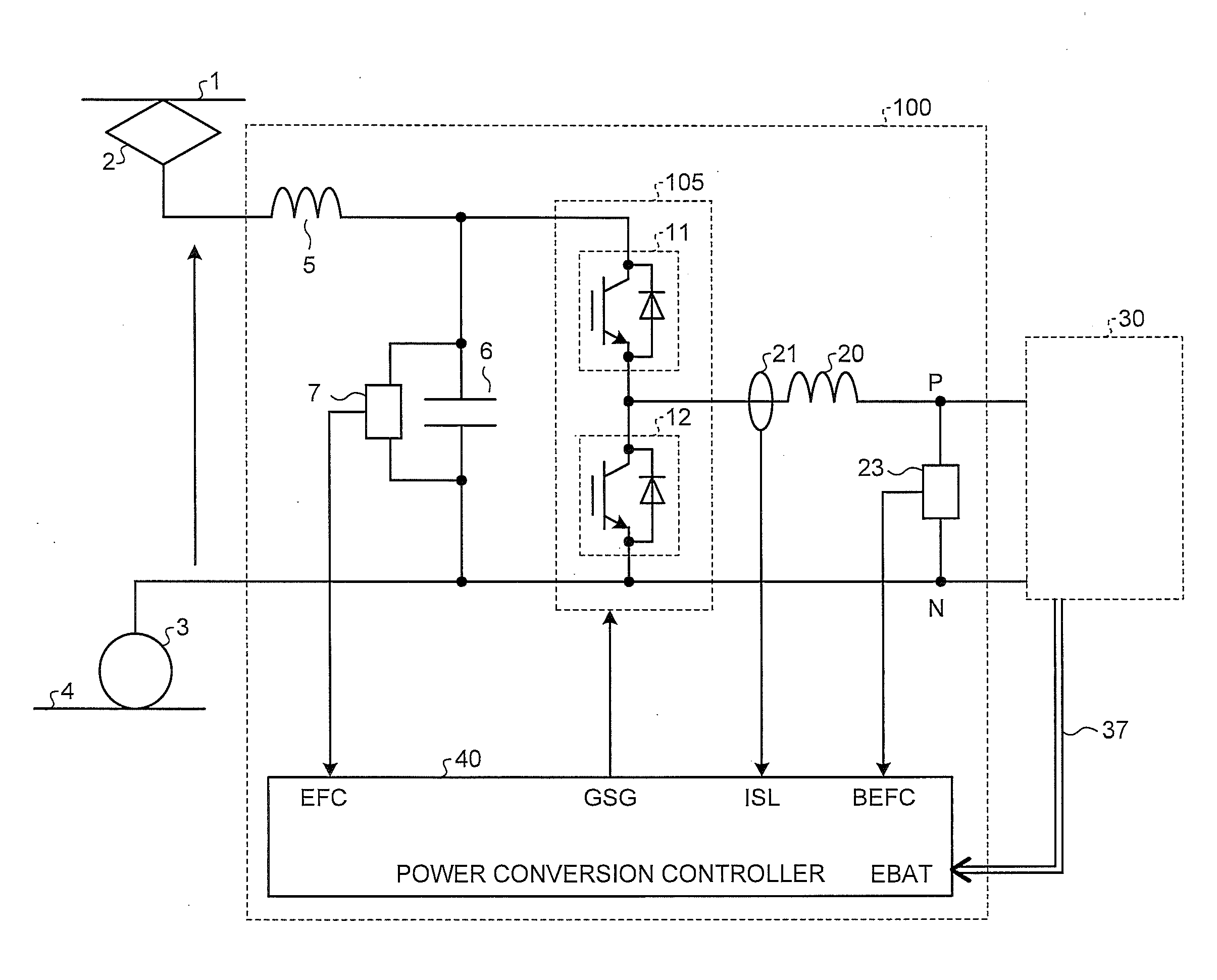
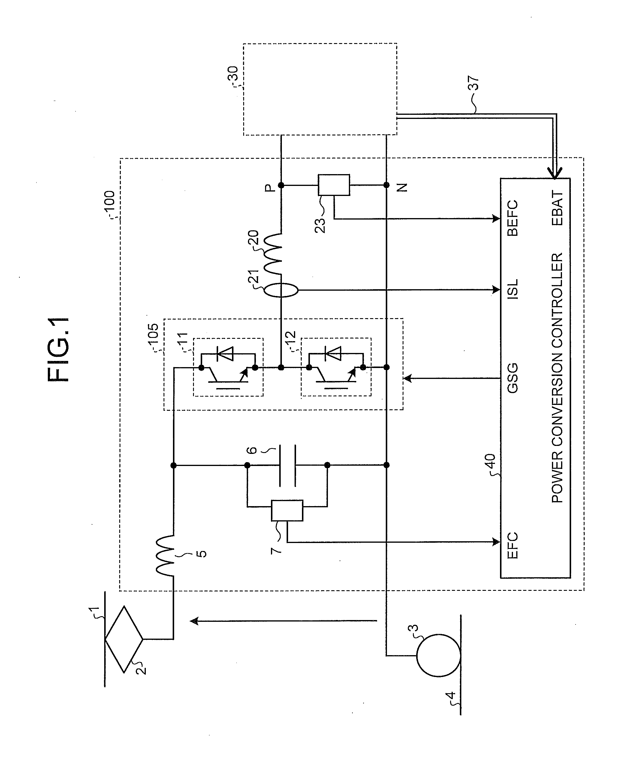
FIG. 1 is a configuration example of a power converter according to an embodiment of the present invention. In FIG. 1, a power converter 100 according to the present embodiment is connected to a wire 1 connected to an electric-power substation (not shown) as a direct-current power source, a power collector 2 that collects power from the wire 1, a wheel 3 that becomes a return circuit of a return current, and a rail 4 that is connected to the electric-power substation. A voltage supplied from the wire 1 is a high voltage of DC600 volts to 3000 volts.
Main circuit configuration elements constituting the power converter 100 include: an LC filter circuit constituted by a reactor 5 as an input reactor to suppress a flow out of a higher harmonic current to an electric-power substa...
PUM
 Abstract
Description
Claims
Application Information